Siemens SIMATIC ET 200S Manual
Distributed i/o 2ai i 4wire st analog electronic module
Hide thumbs
Also See for SIMATIC ET 200S:
- Manual (652 pages) ,
- Operating instructions manual (418 pages) ,
- Installation and operating manual (216 pages)
Table of Contents
Advertisement
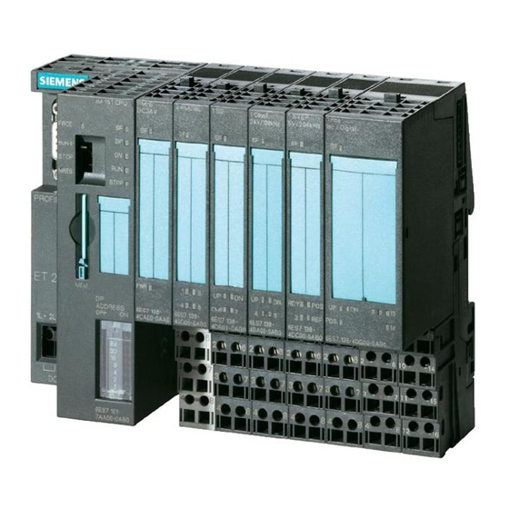
SIMATIC ET 200S distributed I/O 2AI I 4WIRE ST analog electronic module (6ES7134-4GB11-0AB0)
SIMATIC
ET 200S distributed I/O
2AI I 4WIRE ST analog electronic
module (6ES7134-4GB11-0AB0)
Manual
04/2007
A5E01076100-01
Preface
______________
Properties
______________
Parameters
______________
Diagnostics
______________
Analog value representation
______________
Connecting
1
2
3
4
5
Advertisement
Table of Contents


Need help?
Do you have a question about the SIMATIC ET 200S and is the answer not in the manual?
Questions and answers