Table of Contents
Advertisement
Available languages
Available languages
Quick Links
Istruzioni per l'installazione e l'uso
I
Unità Refrigerante
VE150
Installation and usage instructions
EN
Cooling Unit
VE150
Installations- und Wartungsanleitung
DE
Bedienungsanleitung Kühleinheit
VE150
Instructions pour l'installation et l'utilisation
FR
Unité Réfrigérante
VE150
Instrucciones para la instalación y el uso
ES
Unidad Refrigerante
VE150
Advertisement
Table of Contents

Related Manuals for Indel Webasto Marine Isotherm VE150


Summary of Contents for Indel Webasto Marine Isotherm VE150
- Page 1 Istruzioni per l’installazione e l’uso Unità Refrigerante VE150 Installation and usage instructions Cooling Unit VE150 Installations- und Wartungsanleitung Bedienungsanleitung Kühleinheit VE150 Instructions pour l’installation et l’utilisation Unité Réfrigérante VE150 Instrucciones para la instalación y el uso Unidad Refrigerante VE150...
-
Page 3: Sicurezza Generale
Se l’apparecchiatura presenta danni visibili, evitare di metterla in funzione. L’apparecchiatura deve essere riparata solo da personale specializzato (centri Assistenza Indel Webasto Marine), le riparazioni effettuate in modo non adeguato potrebbero causare danni a cose o persone. Non aprire in nessun caso il circuito di raffreddamento. - Page 4 VE150 Cooling Unit INSTALLAZIONE ED USO L’apparecchio refrigerante Isotherm VE150 è progettato specificatamente per l’installazione all’intero di un box appositamente realizzato per la refrigerazione e conservazione degli alimenti, oppure può essere impiegato per refrigerare un vano già esistente non utilizzato.
-
Page 5: Connessioni Elettriche
VE150 Cooling Unit CONNESSIONI ELETTRICHE L’unità elettronica deve essere collegata direttamente alla batteria o all’interruttore principale, protetta da sintemi di sicurezza: fusibile, interruttori automatici o interruttori differenziali nel caso di alimentazione alternata. Il fusibile per la connessione elettrica in corrente continua deve essere almeno di 15A per tensione 12Vdc e almeno 7,5A per tensione 24Vdc. -
Page 6: Schema Elettrico
VE150 Cooling Unit SCHEMA ELETTRICO... - Page 7 VE150 Cooling Unit INSTALLAZIONE DEL GRUPPO EVAPORANTE L’evaporatore deve essere posizionato nella parte più alta all’interno del box/vano in posizione verticale. Vedi figura a lato. Praticare un foro del diametro di 30mm nella parete del box/vano per il passaggio del tubo flessibile con gli attacchi rapidi. Prima di installare il gruppo evaporante, svolgere completamente il tubo mantenendo sempre le coperture di protezione sugli attacchi rapidi finché...
-
Page 8: Manutenzione
VE150 Cooling Unit AVVIAMENTO Effettuare una prova di funzionamento dell’apparecchiatura ruotando in senso orario la manopola del termostato. Il compressore deve avviarsi entro pochi secondi. Controllare che la ventola di raffreddamento del condensatore e quella di distribuzione del gruppo evaporante siano in funzione. Dopo qualche minuto dall’avvio, il gruppo evaporante inizierà... -
Page 9: Troubleshooting
VE150 Cooling Unit Trouble Shooting Problema Motivo Possibile Soluzio- Soluzione Note ne/Controllo Unità Ventilata L’Unità refrige- La tensione dell’ali- L’unità non’è con- Controllare connes- rante non parte mentazione principale nessa o sono inver- sione cavi – Unità nuova è troppo bassa tite le polarità... - Page 10 VE150 Cooling Unit Problema Motivo Possibile Soluzio- Soluzione Note ne/Controllo L’unità lavora per L’unità lavora per Troppo gas caricato Rimuovere il gas in qualche secondo meno di 0,5 sec. eccesso dall’unità. – unità nuova La pressione del gas potrebbe dipendere dalla temperature.
- Page 11 VE150 Cooling Unit Problema Motivo Possibile Soluzio- Soluzione Note ne/Controllo Unità nuova Perdita di gas Chiudere la perdita Mettere il Sistema sotto 1. Il consumo è < tramite saldatura pressione con max. 5bar di del normale. quando possibile o Azoto, ricercare la perdita con 2.
- Page 12 VE150 Cooling Unit Problema Motivo Possibile Soluzio- Soluzione Note ne/Controllo L’unità non si L’alimentazione Connessione Controllare avvia – Unità generale è troppo elettrica connessione elettrica funzionava corret- bassa tamente Controllare la tensione I cavi sono ossidati Termostato Termostato difet- toso! Unità...
-
Page 13: Specifiche Tecniche
VE150 Cooling Unit SICUREZZA Non utilizzare l’apparecchiatura in caso di danni visibili, sia meccanici che elettrici. Non aprire mai il circuito refrigerante, tranne i giunti ad accoppiamento rapido se sono del tipo auto- sigillante e concepiti a tale fine. Verificare che la ventilazione del compressore non sia bloccata. Se è presente un carica batterie, questo deve essere connesso alla batteria e mai direttamente all’unità... -
Page 14: General Safety
The unit must only be installed by qualified personnel. If the unit shows visible signs of damage, do not operate it. The unit must only be repaired by specialised personnel (Indel Webasto Marine Service Centres). Repairs performed inadequately could cause damage and/or injury. -
Page 15: Installation And Use
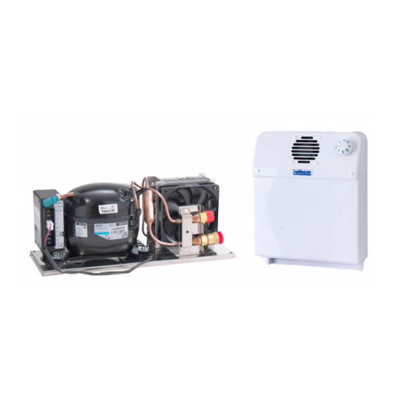
VE150 Cooling Unit INSTALLATION AND USE The Isotherm VE150 cooling unit is specifically designed to be installed inside a box that has been specially made for chilling and storing food, or can be used to chill a compartment that already exists but is not in use. -
Page 16: Electrical Connections
VE150 Cooling Unit ELECTRICAL CONNECTIONS The electronic unit must be connected directly to the battery or the main switch, protected by safety systems: fuses, automatic switches or circuit breakers in the case of AC power. The fuse for the direct current electrical connection must be at least 15 A for 12 VDC and at least 7.5 A for 24 VDC. -
Page 17: Wiring Diagram
VE150 Cooling Unit WIRING DIAGRAM... - Page 18 VE150 Cooling Unit INSTALLING THE EVAPORATOR UNIT The evaporator must be placed at the top inside the box/compartment in an upright position. See the figure on the right. Drill a hole with a 30 mm diameter in the wall of the box/compartment so that the hose with the quick couplings can pass through.
-
Page 19: Maintenance
VE150 Cooling Unit START-UP Test the operation of the unit by turning the thermostat knob in a clockwise direction. The compressor must start up within a few seconds. Check that the condenser cooling fan and the evaporator unit distribution fan work correctly. A few minutes after start-up, the evaporator unit will begin to cool down, producing cold air from the bottom. - Page 20 VE150 Cooling Unit Trouble Shooting Problems Reasons Possible Issue / Solution Notes Check Air cooled The Cooling Unit The main supply volt- The unit is not Check the wire con- does not start - age is too low connect or wrong nection the Unit is new polarity...
- Page 21 VE150 Cooling Unit Problems Reasons Possible Issue / Solution Notes Check The Cooling Unit It works <0.5 sec. Too much gas Remove some gas works for few from the unit. In this seconds - the Unit situation experience is new is very important, gas pressure may vary depending on...
- Page 22 VE150 Cooling Unit Problems Reasons Possible Issue / Solution Notes Check The Unit is new Gas Leakage Where it is possible Put the system on pressure 1. The electrical close the leak with with nitrogen gas max 5 bars consumption is less welding or remove the (70 psi), search the leakage than normal...
- Page 23 VE150 Cooling Unit Problems Reasons Possible Issue / Solution Notes Check The Cooling Unit The main supply Electrical Check the wire does not start - voltage is too low connection connection the Unit worked Check the voltage The wires are oxidized Thermostat Thermostat is...
-
Page 24: Technical Data
VE150 Cooling Unit SAFETY Do not use the unit if there is visible damage, be it mechanical or electrical. Never open the cooling circuit, except for the quick coupling joints if they are self-sealing and designed for this purpose. Check that compressor ventilation is not blocked. If there is a battery charger, it must be connected to the battery and never directly to the cooling unit. - Page 25 Si l’appareil présente des dommages visibles, éviter de le mettre en service. L’appareil doit être réparé uniquement par du personnel spécialisé (centres d’Assistance Indel Webasto Marine), les réparations effectuées de façon non-conforme pourraient causer des dommages aux personnes et aux appareils.
- Page 26 VE150 Cooling Unit INSTALLATION ET EMPLOI L’appareil réfrigérant Isotherm VE150 est conçu spécialement pour l’installation à l’intérieur d’un coffre réalisé spécialement pour la réfrigération et la conservation des aliments, ou pour être utilisé pour refroidir un compartiment déjà existant non utilisé.
-
Page 27: Branchements Electriques
VE150 Cooling Unit BRANCHEMENTS ELECTRIQUES L’unité électronique doit être branchée directement à la batterie ou à l’interrupteur principal, protégée par des systèmes de sécurité: fusible, interrupteurs automatiques ou différentiels en cas d’alimentation alternative. Le fusible pour le branchement électrique en courant continu doit être d’au moins 15A pour une tension de 12Vdc et d’au moins 7,5A pour une tension de 24Vdc. -
Page 28: Schema Electrique
VE150 Cooling Unit SCHEMA ELECTRIQUE... - Page 29 VE150 Cooling Unit INSTALLATION DU GROUPE EVAPORATEUR L’évaporateur doit être positionné dans la partie la plus haute à l’intérieur du coffre/ compartiment en position verticale. Voir figure ci-contre. Pratiquer un trou d’un diamètre de 30 mm dans la paroi du coffre/compartiment pour le passage du tuyau flexible avec les raccords rapides.
-
Page 30: Mise En Marche
VE150 Cooling Unit MISE EN MARCHE Effectuer un essai de fonctionnement de l’appareil en tournant le bouton du thermostat dans le sens des aiguilles d’une montre. Le compresseur doit démarrer dans les secondes qui suivent. Contrôler que le ventilateur de refroidissement du condensateur et celui de distribution du groupe évaporateur fonctionnent. - Page 31 VE150 Cooling Unit Dépannages Problèmes Causes Emission possible Solution Notes / Contrôle Refroidi à air L’Unité de refroi- La tension d’alimen- L’appareil n’est pas Contrôler le branche- dissement ne tation principale est connecté ou a une ment des fils démarre pas - trop basse polarité...
- Page 32 VE150 Cooling Unit Problèmes Causes Emission possible Solution Notes / Contrôle L’Unité de re- Elle fonctionne <0,5 Trop de gaz Enlever du gaz de froidissement sec. l’appareil. Dans cette ne travaille que situation l’expérience pendant quelques est très importante la secondes L’appa- pression du gaz peut reil est neuf...
- Page 33 VE150 Cooling Unit Problèmes Causes Emission possible Solution Notes / Contrôle L’appareil est neuf Lorsque c’est possible Mettre l’appareil à une pres- Fuite Gaz 1. La consommation colmater la fuite par sion avec de l’azote max 5 électrique est infé- une soudure ou enle- bars (70 psi), chercher la fuite rieure à...
- Page 34 VE150 Cooling Unit Problèmes Causes Emission possible Solution Notes / Contrôle L’Unité de refroi- La tension principale Branchement Contrôler Branchement dissement ne d’alimentation est électrique électrique démarre pas - trop basse L’appareil a déjà Contrôler la tension fonctionné Les fils sont oxydés Thermostat Le thermostat est à...
-
Page 35: Specifications Techniques
VE150 Cooling Unit SECURITE Ne pas utiliser l’appareil s’il présente des dommages visibles, mécaniques ou électriques. Ne jamais ouvrir le circuit réfrigérant, sauf les joints à accouplement rapide s’ils sont du type auto- obturateur et conçus dans ce but. Vérifier que la ventilation du compresseur n’est pas bloquée. Si un chargeur de batterie est présent, il doit être branché... -
Page 36: Allgemeine Sicherheitshinweise
Das Gerät ausschließlich von Fachpersonal installieren lassen. Bei offensichtlichen Geräteschäden den Gerätebetrieb vermeiden. Für die Instandsetzung des Geräts ist ausschließlich qualifiziertes Fachpersonal zuständig (Kundendienstzentren Indel Webasto Marine), unsachgemäße Instandsetzungsmaßnahmen können Personen- und Geräteschäden zur Folge haben. Den Kühlkreislauf des Geräts unter keinen Umständen öffnen. - Page 37 VE150 Cooling Unit INSTALLATION UND GEBRAUCH Das Kühlgerät Isotherm VE150 wurde speziell zur Installation in einem eigens dafür gefertigten Gehäuse zur Kühlung und Aufbewahrung von Lebensmitteln konzipiert, kann aber auch zur Kühlung eines bereits vorhandenen, aber ungenutzten Raumes verwendet werden.
- Page 38 VE150 Cooling Unit STROMANSCHLUSS Die elektronische Steuerung muss direkt an den durch Sicherheitsvorrichtungen geschützten Akku oder Hauptschalter angeschlossen werden. Geeignete Vorrichtungen sind: Schmelzsicherungen, Automatik- oder Differentialschalter bei Wechselstrom. Mindestvoraussetzungen für die Schmelzsicherung bei Gleichstrom: 15A bei 12Vdc Spannung, mindestens 7,5A bei 24Vdc Spannung. Unbedingt auf den korrekten Querschnitt des Hauptversorgungskabels achten.
- Page 39 VE150 Cooling Unit SCHALTPLAN...
- Page 40 VE150 Cooling Unit INSTALLTION DER VERDAMPFEREINHEIT Der Verdampfer muss im oberen Bereich des Gehäuses/Raums in vertikaler Position installiert werden. Siehe nebenstehende Abbildung. Eine Bohrung mit 30mm Durchmesser an der Wand des Gehäuses/Raums zum Verlegen der Schlauchleitung mit den Schnellsteckverbindern ausführen. Vor der Installation der Verdampfereinheit den Schlauch vollständig ausrollen.
-
Page 41: Wartung
VE150 Cooling Unit INBETRIEBNAHME Zum Durchführen eines Funktionstests des Geräts den Griff des Thermostats im Uhrzeigersinn drehen. Der Verdichter muss innerhalb weniger Sekunden anlaufen. Sicherstellen, dass das Kühlgebläse des Verdichters und das Verteilergebläse des Verdampfers laufen. Wenige Minuten nach dem Einschalten beginnt der Verdampfer mit der Kühlung und bildet von innen heraus kalte Luft. - Page 42 VE150 Cooling Unit Trouble Shooting Probleme Ursachen Möglicher Fehler/ Lösung Hinweise Überprüfung Luftkühlung Kühleinheit läuft Versorgungsspannung Nicht korrekter Kabelanschluss prüfen nicht an – neues zu niedrig Stromanschluss Gerät des Geräts; Falsche Polung Kabelquerschnitt zwischen Akku und elektronischer 101N0210.pdf Steuerung prüfen Spannungsversor- Akku aufladen - gung der Verbindung...
- Page 43 VE150 Cooling Unit Probleme Ursachen Möglicher Fehler/ Lösung Hinweise Überprüfung Kühleinheit läuft Funktioniert <0,5 Sec. Zu viel Kältemittel Etwas Kältemittel aus nur wenige Se- der Einheit ablassen. kunden – neues Dabei ist Erfahrung Gerät erforderlich, da der Gasdruck auch tem- peraturabhängig ist.
- Page 44 VE150 Cooling Unit Probleme Ursachen Möglicher Fehler/ Lösung Hinweise Überprüfung Neues Gerät Kältemittelleckage Leckage wenn möglich Im System mit Stickstoffgas ei- 1. Stromverbrauch verschweißen oder nen Druck von max. 5 bar (70 niedriger als Stelle mit Loch ent- psi) aufbauen und die Leckage normal fernen.
- Page 45 VE150 Cooling Unit Probleme Ursachen Möglicher Fehler/ Lösung Hinweise Überprüfung Kühleinheit läuft Versorgungsspannung Stromanschluss Kabelanschluss nicht an – bisher zu niedrig überprüfen korrekter Geräte- betrieb Check the voltage The wires are oxidized Thermostat Thermostat is broken! Faulty electronic Unit Alles korrekt ins- Stromverbrauch Verdichter auswech- talliert, Kältemittel...
-
Page 46: Technische Spezifikation
VE150 Cooling Unit SICHERHEIT Das Gerät bei offensichtlichen mechanischen oder elektrischen Schäden nicht verwenden. Den Kühlkreislauf niemals öffnen, außer an den eigens dafür konzipierten, selbstisolierenden Schnellsteckverbindern. Sicherstellen, dass der Verdichter korrekt belüftet ist. Bei vorhandenem Akku-Ladegerät darauf achten, dass dies am Akku und niemals direkt an der Kühleinheit angeschlossen ist. TECHNISCHE SPEZIFIKATION DC Versorgung: 12/24Vdc... -
Page 47: Seguridad General
VE150 Cooling Unit Antes de poner en funcionamiento el equipo, leer cuidadosamente este manual de instrucciones, conservarlo y, en caso de reventa, entregarlo al cliente siguiente. ADVERTENCIAS La falta de cumplimiento de las indicaciones puede causar daños a personas y aparatos No está... -
Page 48: Instalación Y Uso
VE150 Cooling Unit INSTALACIÓN Y USO El aparato refrigerante Isotherm VE150 ha sido proyectado específicamente para la instalación dentro de un box especialmente realizado para la refrigeración y conservación de los alimentos o bien puede ser utilizado para refrigerar un compartimiento ya existente no utilizado. -
Page 49: Conexiones Eléctricas
VE150 Cooling Unit CONEXIONES ELÉCTRICAS La unidad electrónica debe conectarse directamente a la batería o al interruptor principal, protegida por sistemas de seguridad: fusible, interruptores automáticos o interruptores diferenciales en el caso de corriente alterna. El fusible para la conexión eléctrica en corriente continua debe ser de por lo me- nos 15 A para tensión de 12 Vdc y de por lo menos 7,5 A para tensión de 24 Vdc. -
Page 50: Esquema Eléctrico
VE150 Cooling Unit ESQUEMA ELÉCTRICO... - Page 51 VE150 Cooling Unit INSTALACIÓN DEL GRUPO EVAPORADOR El evaporador debe colocarse en la parte más alta dentro del box/compartimiento en posición vertical. Ver figura de al lado. Realizar un agujero con un diámetro de 30 mm en la pared del box/compartimiento para el paso del tubo flexible con las conexiones rápidas.
-
Page 52: Puesta En Marcha
VE150 Cooling Unit PUESTA EN MARCHA Ejecute una prueba de funcionamiento del aparato girando en sentido horario el mando del termos- tato. El compresor debe ponerse en marcha dentro de pocos segundos. Controlar que el ventilador de enfriamiento del condensador y el de la distribución del grupo evaporador estén en funcionamiento. Pasados algunos minutos desde la puesta en marcha, el grupo evaporador comenzará... -
Page 53: Solución De Problemas
VE150 Cooling Unit Solución de Problemas Problema Motivo Posible Solución/ Solución Notas Control Unidad Ventilada La Unidad refrige- La corriente de ali- La unidad no está Controlar la conexión rante no se pone mentación principal es conectada o se han de los cables en marcha - Unidad demasiado baja. - Page 54 VE150 Cooling Unit Problema Motivo Posible Solución/ Solución Notas Control La unidad trabaja La unidad trabaja Demasiado gas Sacar de la unidad durante algunos menos de 0,5 seg. cargado el gas en exceso. La segundos - unidad presión del gas po- nueva dría depender de la alta temperatura.
- Page 55 VE150 Cooling Unit Problema Motivo Posible Solución/ Solución Notas Control Unidad nueva Pérdidas de gas Cerrar la pérdida Poner el Sistema bajo presión 1. El consumo es < al mediante soldadura con un máx. de 5 bar de Nitró- normal. cuando sea posible o geno, buscar la pérdida con el 2.
- Page 56 VE150 Cooling Unit Problema Motivo Posible Solución/ Solución Notas Control La unidad no se La alimentación Conexión eléctrica Controlar la conexión pone en marcha general es demasiado eléctrica - La unidad fun- baja cionaba correcta- Controlar la ten- mente sión Los cables están oxidados Termostato...
-
Page 57: Especificaciones Técnicas
VE150 Cooling Unit SEGURIDAD No utilizar el aparato en caso de daños visibles, ya sea mecánicos o eléctricos. Nunca abrir el circuito refrigerante, excepto las uniones de acople rápido si son de tipo auto sellantes y diseñadas para ello. Comprobar que la ventilación del compresor no esté bloqueada. Si la instalación cuenta con un cargador de baterías, éste debe conectarse a la batería, no directamente a la unidad de refrigeración ESPECIFICACIONES TÉCNICAS Alimentación DC:... - Page 60 Indel Webasto Marine Srl Indel Webasto Marine USA Zona Artigianale sn 3391 SW 42nd Street 47866 - Sant’Agata Feltria (RN) - ITALY Hollywood, FL 33312 Tel. +39 0541 848030 - Fax +39 0541 848 563 Phone (954) 984 8448 - Fax (954) 979 2533 E-MAIL: info@indelwebastomarine.com...
Need help?
Do you have a question about the Isotherm VE150 and is the answer not in the manual?
Questions and answers