BFT E5 BT A18 Installation And User Manual
Arm automations for swing gates
Hide thumbs
Also See for E5 BT A18:
- Installation and user manual (16 pages) ,
- Installation and user manual (14 pages)

Related Manuals for BFT E5 BT A18


Summary of Contents for BFT E5 BT A18
- Page 1 E5 BT A18 E5 BT A12 E5 BT A18 E5 BT A18 E5 BT A12 E5 BT A12 D814068 0AA00_04 19-03-20 INSTALLATION AND USER’S MANUAL ARM AUTOMATIONS FOR SWING GATES Caution! Read “Warnings” inside carefully!
- Page 2 Total safety against crushing is ensured by a multiple disc clutch, and the end-of-stroke operation is regulated with an encoder. PREPARATION OF CABLES 3 x 1 mm Not supplied E5 BT A18 - E5 BT A12...
-
Page 3: Package Contents
Achtung! Bitte lesen Sie aufmerksam die „Hinweise“ im Inneren! ¡Atención¡ Leer atentamente las “Advertencias” en el interior! Let op! Lees de “Waarschuwingen” aan de binnenkant zorgvuldig! M8x80 M10x25 3.5x9.5 PG 16 E5 BT A18 E5 BT A18 E5 BT A12 E5 BT A12 ACCESSORY ARM NOT SUPPLIED articulated arm slide arm slide arm E5 BT A18 - E5 BT A12 -... -
Page 4: Equipment Required
EQUIPMENT REQUIRED Ø6 Ø10 Iron Wall DIMENSIONS E5 BT A18 - E5 BT A12... - Page 5 ACCESSORY ARTICULATED ARM FOR E5 BT A18 / E5 BT A12 EQUIPMENT REQUIRED PACKAGE CONTENTS M10x40 M10 10.5x20x2 DIMENSIONS A+C 470 - 530 > 280 WARNING! Place the bracket on the full part of the gate. 125° 130° 134° 134°...
- Page 6 ACCESSORY SLIDE ARM FOR E5 BT A18 EQUIPMENT REQUIRED PACKAGE CONTENTS 12.2x18x1 13x24x2.5 Ø16x12 16x26x1.5 M12x60 H=12 DIMENSIONS >50 α C > 1000 1020 1020 1100 1120 WARNING! Place the bracket on the full part of the gate. E5 BT A18 - E5 BT A12...
- Page 7 Ø6 / Ø12 13x24x2.5 Ferro Ø16x12 Iron 16x26x1.5 M12x60 H=12 Eisen Hierro Ijzer DIMENSIONS α C > 1010 1030 WARNING! Place the bracket on the full part of the gate. Ø12 Ø12 Ø6 Ø6 E5 BT A18 - E5 BT A12 -...
- Page 8 FASTENING OF MOTOR HOLDER PLATE ON METAL oder ON THE WALL Use stainless steel dowels! Not supplied! E5 BT A18 - E5 BT A12...
-
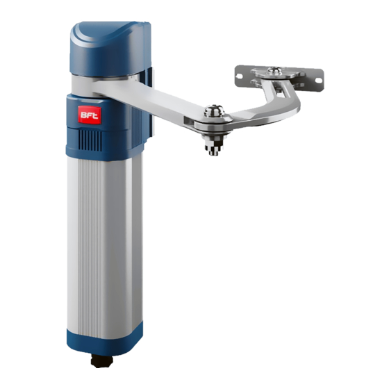
Page 9: Articulated Arm
FASTENING OF BRACKET ON LEAF ARTICULATED ARM E5 BT A18 5.25 MAX M6 SLIDE ARM E5 BT A18 E5 BT A12 Not supplied - E5 BT A18 - E5 BT A12 -... - Page 10 F2 3,15 AT 10 11 14 15 20 21 26 27 40 41 42 43 44 45 50 51 52 60 61 62 70 71 72 73 74 75 Brown Green Yellow Bleu 10 - E5 BT A18 - E5 BT A12...
-
Page 11: Motor Installation
MOTOR INSTALLATION ASSEMBLY AND FASTENING OF ARTICULATED ARM E5 BT A18 Secure and make sure that the arm is freed to move. 10.5 E5 BT A18 - E5 BT A12 -... - Page 12 ASSEMBLY AND FASTENING OF SLIDE ARM 90° E5 BT A18 Ø16x12 H=12 Ø16x12 H=12 Grease 12.2 90° Ø16x12 H=12 E5 BT A12 Ø16x12 H=12 Grease 12 - E5 BT A18 - E5 BT A12...
-
Page 13: Technical Data
-20 / +55° C Lubrication permanent grease Degree of protection IP44 Actuator weight 50 N (5kg) 50 N (5kg) Sound pressure <70dB(A) * special voltage supplies on request only for E5 BT A18 E5 BT A18 - E5 BT A12 -... - Page 14 CLUTCH FASTENING E5 BT A18 - E5 BT A12 -...
- Page 15 www.bftme.ae...
Need help?
Do you have a question about the E5 BT A18 and is the answer not in the manual?
Questions and answers