Table of Contents
Advertisement
Quick Links
Bedienungsanleitung
1-Kanal Lichtschrankenverstärker
ISG-A104...
Sicherheitshinweise
Der Einsatz von Infrarot-Verstärkern ISG-A104... ist nicht zulässig für Anwendungen,
bei denen die Sicherheit von Personen von der Gerätefunktion abhängig ist.
Der Betreiber des übergeordneten Systems, z.B. einer Maschinenanlage,
ist für die Einhaltung der nationalen und internationalen Sicherheits- und
Unfallverhütungsvorschriften verantwortlich.
• Einleitung
Die Lichtschrankenverstärker werden zur Erkennung von Objekten in Maschinen oder
Produktionsanlagen eingesetzt. Sie bilden in Verbindung mit einem Infrarotsender IT...
und Infrarotempfänger IR... (nicht im Lieferumfang) eine leistungsstarke Lichtschranke
und sind einsetzbar in Bereichen mit hoher Reichweite oder Verschmutzung.
• Arbeitsweise
Die Geräte der Serie ISG-A104... sind 1-Kanal-Automatik-Verstärker bei denen kein
Einstellen oder Nachstellen erforderlich ist. Sie erkennen beim Einschalten den
Montageabstand, pegeln sich sekundenschnell optimal ein und regeln auf das System
einwirkende Störeinflüsse permanent und zu 100 % aus.
Der Verstärker arbeitet mit moduliertem Infrarotlicht, wodurch eine hohe Sicherheit
gegen Fremdlicht erreicht wird. Die Schaltung ist so ausgelegt, daß nur Signale
richtiger Frequenz und Phasenlage erkannt werden. Dadurch ist eine Beeinflussung
durch andere Lichtschranken nahezu ausgeschlossen.
• Montage
Die Verstärker sind für eine schnelle Montage und Demontage konzipiert und besitzen
daher einen Steckanschluß. Um eine sichere Funktion zu garantieren und eine
Beschädigung des Gerätes zu vermeiden, immer einen Stecksockel benutzen.
• Anschlußschema / Wiring diagram
Betriebsspannung
Supply voltage
• Betriebsspannung
Die Betriebsspannungsangabe ist in den letzten
zwei oder drei Nummern der Gerätebezeichnung
enthalten (siehe rückseitiges Typenschild).
Bei 24 V DC ein passend dimensioniertes UL Class
2 Netzteil verwenden.
• Funktionen
Die Funktionen sind mit dem DIP-Schalter auf der
Geräterückseite einzustellen. Die Schaltfunktion wird
über PIN 11 eingestellt (siehe Anschlußschema).
– Schaltfunktion
Die Schaltfunktion beschreibt das Verhalten des Schaltausganges beim Unterbrechen
des Infrarotstrahls. Bei Dunkelschaltung erfolgt bei unterbrochener Lichtstrecke ein
Ausgangssignal. In Hellschaltung erfolgt bei freier Lichtstrecke ein Ausgangssignal.
– Grundleistung
Die Grundleistung gibt an, wie der Verstärker die Leistung regelt.
Low 1: Der Sendestrom wird auf den optimalen Wert für die Strecke eingestellt
(empfindlichste Einstellung).
Low 2: Wie Low 1, aber der Verstärker ist unempfindlicher (benötigt eine höhere
Streckendämpfung, um eine Änderung am Schaltausgang zu erzeugen).
High 1: Der Sendestrom beträgt mindestens 50 % des Maximalwertes.
High 2: Der Sendestrom beträgt mindestens 90 % des Maximalwertes.
– Sendefrequenz
Bei der Montage mehrerer Sensoren dicht nebeneinander, ist ein Betrieb der Verstärker
bei verschiedenen Sendefrequenzen noch möglich. Jeder Verstärker wertet nur das
Signal mit der eigenen Sendefrequenz aus.
• DIP-Schaltereinstellung
1
Grundleistung
High 2
ON
High 1
ON
Low 2
OFF
Low 1
OFF
Werkseinstellung grau hinterlegt
OI140616DE/EN
Sender
Transmitter
Relais
Relay
Rot/
COM
NO
NC
Schwarz/
Red
Black
7
Ground
DIP-Schalter
Stecker
Typenschild
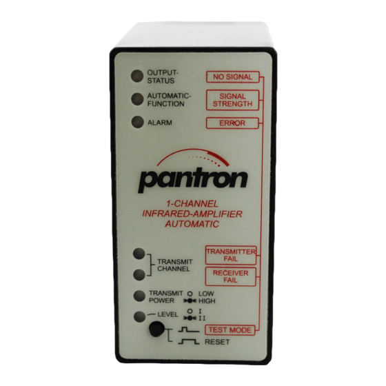
IR-Amplifier
Automatic
ISG-A104/230VAC
Betriebsspannung
zum Beispiel: 230VAC
2
3
4
Sendefrequenz
ON
4,10 kHz
ON
ON
OFF
3,97 kHz
ON
OFF
ON
3,85 kHz
OFF
ON
OFF
3,70 kHz
OFF
OFF
Alle technischen Angaben beziehen sich auf den Stand 12/2015. Änderungen bleiben vorbehalten.
All technical specifications refer to the state of the art 12/2015. They are subject to modifications.
Operating Instructions
1-channel light barrier amplifier
ISG-A104...
Safety instructions
The operation of infrared amplifier ISG-A104... is not authorized for applications
where the safety of a person depends on the function of the device.
The operator of the higher-level overall system, e.g. a machine installation,
is responsible for complying with the national and international safety and
accident prevention regulations which apply to the specific use.
• Introduction
The light barrier amplifiers are used for the detection of objects in machines or production
systems. They form, in conjunction with one infrared transmitter and receiver (not
included in delivery), a powerful light barrier and they are useable in areas with long
range or an extreme degree of pollution.
• Principle of operation
The devices of the series ISG-A104... are 1-channel automatic amplifiers, which need no
adjustments. After switching on the voltage supply, the eyes detect the range between
them and adjust the transmit power to the optimum level.
The amplifier works with modulated infrared light which provides high immunity to
ambient light. The electronic circuits are designed to detect only those signals with the
correct frequency and phase relation. This almost completely excludes interference
from other light barriers.
• Installation
The device includes a plug for simple installation. As a safe operating procedure and
to avoid damaging the device, use an 11-PIN socket.
Empfänger
Receiver
Alarmausgang
Alarm output
pnp
Gelb/
Schirm/
Yellow
Shield
24 VDC
• Supply voltage
The supply voltage is the last two or three numbers
of the part number. On the bottom of the amplifier
is the type plate with the part number.
24V DC to be provided by a suitably rated UL Listed
Class 2 power supply.
• Functions
The functions are selectable by DIP-switches on
the bottom of the amplifier. The switching mode is
selectable by PIN 11 (see wiring diagram).
– Switching mode
The switching mode determines the output behavior upon interruption of the infrared
beam. When the amplifier is set to dark mode, there is a output signal as long as the
beam is broken. In light mode, there is an output signal when the beam is present.
– Basic transmit level
The basic transmit level is the minimum transmit power level on an infrared amplifier
Low 1: The transmit power level is always set to the optimal value for constant high
switching sensitivity.
Low 2: The amplifier works like Low 1 basic transmit level but the device is less
sensitive.
High 1: The transmit power is always at least 50 % of the maximum power level.
High 2: The transmit power is always at least 90 % of the maximum power level.
– Transmit frequency
The transmit frequency means the modulation frequency at which the amplifier works.
If more than one sensor head is mounted side by side, the amplifier must be set to
different frequencies.
• DIP switch setting
1
Basic transmit power
High 2
ON
High 1
ON
Low 2
OFF
Low 1
OFF
Factory setting is marked in grey
Schaltfunktion
Switching mode
Offen / Open = dunkel / dark
0 V = hell / light
7
DIP-switch
Plug
Type plate
IR-Amplifier
Automatic
ISG-A104/230VAC
Supply voltage
for example: 230VAC
2
3
4
Transmit frequency
ON
4,10 kHz
ON
ON
OFF
3,97 kHz
ON
OFF
ON
3,85 kHz
OFF
ON
OFF
3,70 kHz
OFF
OFF
1
/2
Advertisement
Table of Contents

Subscribe to Our Youtube Channel
Related Manuals for Pantron ISG-A104 Series


Summary of Contents for Pantron ISG-A104 Series
- Page 1 Bedienungsanleitung Operating Instructions 1-Kanal Lichtschrankenverstärker 1-channel light barrier amplifier ISG-A104... ISG-A104... Sicherheitshinweise Safety instructions Der Einsatz von Infrarot-Verstärkern ISG-A104... ist nicht zulässig für Anwendungen, The operation of infrared amplifier ISG-A104... is not authorized for applications bei denen die Sicherheit von Personen von der Gerätefunktion abhängig ist. where the safety of a person depends on the function of the device. Der Betreiber des übergeordneten Systems, z.B.
- Page 2 Operating temperature Lagertemperatur -40 °C ... + 80 °C (-40 °F ... +176 °F) Storage temperature Prüfungen Approvals Tel. +49 (0) 5063 / 9591-0 Pantron Instruments GmbH +49 (0) 5063 / 9591-55 Süllbergstraße 3-5 E-mail sales@pantron.de D-31162 Bad Salzdetfurth Internet www.pantron.de...
Need help?
Do you have a question about the ISG-A104 Series and is the answer not in the manual?
Questions and answers