Witt HRP 5040 Installation And Operating Instructions Manual
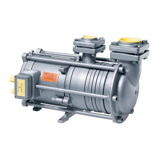
Hermetic refrigerant pump
Hide thumbs
Also See for HRP 5040:
- Installation & operation manual (50 pages) ,
- Installation and operating instructions manual (46 pages) ,
- Quick start manual (4 pages)
Table of Contents
Advertisement
Quick Links
MONTAGE- UND BETRIEBSANLEITUNG
INHALTSVERZEICHNIS
1.
EINLEITUNG .........................................................................2
1.1
VERWENDUNGSZWECK................................................2
1.2
SICHERHEITSBESTIMMUNGEN ....................................2
1.3
SICHERHEITSHINWEISE................................................3
1.4
HAFTUNGSAUSSCHLUSS .............................................3
2.
GEWÄHRLEISTUNGSBESTIMMUNGEN ............................4
3.
TECHNISCHE INFORMATION .............................................5
3.1
TYPENBEZEICHNUNG ...................................................5
3.2
LIEFERUMFANG .............................................................5
3.3
BESTELLANGABEN ........................................................5
3.4
NORMEN UND BESCHEINIGUNGEN.............................5
4.
TECHNISCHE DATEN ..........................................................6
4.1
ALLGEMEINE DATEN .....................................................6
4.2
ELEKTRISCHE DATEN ...................................................6
4.3
MATERIALIEN..................................................................7
4.4
DRUCKBEREICHE ..........................................................7
4.5
ABMESSUNGEN..............................................................8
4.6
TEILELISTE....................................................................11
4.7
SCHNITTZEICHNUNG...................................................12
4.8
FUNKTIONSBESCHREIBUNG ......................................14
4.9
KENNLINIEN-VERLAUF ................................................14
5.
PLANUNGSHINWEISE .......................................................15
5.1
ALLGEMEINES ..............................................................15
5.2
BESTIMMUNG DER FÖRDERMENGE .........................16
5.3
ANPASSEN AN DIE ANLAGENBEDINGUNGEN ..........17
6.
INSTALLATIONSVORSCHRIFTEN....................................18
6.1
PUMPENANORDNUNG.................................................18
6.2
PUMPENANSCHLUSS ..................................................18
6.3
GESTALTUNG DES PUMPENZULAUFS ......................19
6.4
PUMPENDRUCKLEITUNG............................................20
6.5
ELEKTRISCHER ANSCHLUSS / ABSICHERUNG........20
7.
MONTAGE UND BEDIENUNG ...........................................27
7.1
MONTAGEVORBEREITUNG.........................................27
7.2
MONTAGE DER PUMPE ...............................................27
7.3
VORBEREITUNG DER INBETRIEBNAHME .................28
7.4
INBETRIEBNAHME........................................................29
7.5
NORMALBETRIEB.........................................................29
7.6
PUMPE IM STILLSTAND (STAND-BY) .........................29
8.
WARTUNG UND INSTANDHALTUNG ...............................30
8.1
AUSBAU DER PUMPE ..................................................30
8.2
VERSAND DER PUMPE................................................30
8.3
ALLGEMEINE HINWEISE..............................................31
8.4
REPARATUREN AN DER PUMPE ................................31
8.5
BESONDERE HINWEISE ..............................................32
Hersteller / manufacturer
TH. Witt Kältemaschinenfabrik GmbH
Lukasstrasse 32
52070 Aachen, Germany
Tel. +49-241-18208-0 * Fax. +49-241-18208-49
Angaben gültig ab dem 1.11.2001
Alle Rechte vorbehalten.
Es gelten unsere Liefer- und Montagebedingungen 558 und 188.
HRP
1.
INTRODUCTION ................................................................... 2
1.1
INTENDED USE............................................................... 2
1.2
SAFETY REQUIREMENTS ............................................. 2
1.3
SAFETY ADVICE .............................................................3
1.4
DISCLAIMER ...................................................................3
2.
TERMS OF WARRENTY.......................................................4
3.
TECHNICAL INFORMATION................................................ 5
3.1
DESCRIPTION OF TYPES .............................................. 5
3.2
SCOPE OF DELIVERY .................................................... 5
3.3
ORDERINFORMATION ................................................... 5
3.4
CODES / CERTIFICATES / APPROVALS....................... 5
4.
TECHNICAL DATA ............................................................... 6
4.1
GENERAL INFORMATION .............................................. 6
4.2
ELECTRICAL DATA......................................................... 6
4.3
MATERIALS ..................................................................... 7
4.4
PRESSURE RANGE........................................................ 7
4.5
DIMENSIONS...................................................................8
4.6
PARTS LIST................................................................... 11
4.7
SECTIONAL VIEW OF THE PUMP ............................... 12
4.8
DESCRIPTION OF OPERATION................................... 14
4.9
PERFORMANCE CHARACTERISTIC TABLE .............. 14
5.
APPLICATIONS .................................................................. 15
5.1
GENERAL ...................................................................... 15
5.2
DETERMINATION OF THE REQUIRED FLOW ............ 16
5.3
ADAPTATION TO PLANT REQUIREMENTS................ 17
6.
INSTALLATION INSTRUCTIONS ...................................... 18
6.1
PUMP ARRANGEMENT ................................................ 18
6.2
PUMP CONNECTION.................................................... 18
6.3
DOWNLEG DESIGN ...................................................... 19
6.4
PUMP DISCHARGE LINE.............................................. 20
6.5
SAFETY AND ELECTRICAL INFORMATION ............... 20
7.
INSTALLATION AND APPLICATION ................................ 27
7.1
PREPARING THE PUMP FOR INSTALLATION ........... 27
7.2
MOUNTING INSTRUCTIONS........................................ 27
7.3
PRIOR TO COMMISSIONING ....................................... 28
7.4
COMMISSIONING PROCEDURE ................................. 29
7.5
DURING NORMAL OPERATION................................... 29
7.6
PUMP STANDSTILL (STAND-BY)................................. 29
8.
SERVICE AND MAINTANANCE......................................... 30
8.1
REMOVING A PUMP ..................................................... 30
8.2
SHIPPING OF THE PUMP............................................. 30
8.3
GENERAL ADVICE........................................................ 31
8.4
REPARING A PUMP...................................................... 31
8.5
WARNINGS.................................................................... 32
Data valid from 1.11.2001.
All rights reserved, subject to alterations without notice.
Our terms of delivery 558 and 188 are valid for all sales.
OPERATION & SERVICE MANUAL
CONTENTS
Advertisement
Table of Contents

Related Manuals for Witt HRP 5040


Summary of Contents for Witt HRP 5040
-
Page 1: Table Of Contents
REPARATUREN AN DER PUMPE ........31 REPARING A PUMP............31 BESONDERE HINWEISE ..........32 WARNINGS..............32 Hersteller / manufacturer TH. Witt Kältemaschinenfabrik GmbH Lukasstrasse 32 52070 Aachen, Germany Tel. +49-241-18208-0 * Fax. +49-241-18208-49 Angaben gültig ab dem 1.11.2001 Data valid from 1.11.2001. -
Page 2: Einleitung
Wartungsarbeiten durchführen wollen. VERWENDUNGSZWECK INTENDED USE Die WITT Hermetische Kältemittelpumpe Typ HRP ist aus- The WITT hermetic refrigerant pump type is designed to schließlich zur Förderung eines Kältemittels im Siedezu- deliver exclusively refrigerant liquid at its boiling point. stand bestimmt. -
Page 3: Sicherheitshinweise
Die angegebenen Temperatur- und Druckangaben Under no circumstances are the indicated tem- dürfen auf keinen Fall überschritten werden. perature- and pressure limitations to be ex- ceeded. Achtung! Dem Inhalt dieser Betriebsanleitung ist Important! The content of this manual must be unbedingt Folge zu leisten! Abweichender Einsatz adhered to. -
Page 4: Gewährleistungsbestimmungen
Umbauten vorgenommen werden, die durch die carried out to the refrigerant pump without the explicit TH. WITT KÄLTEMASCHINENFABRIK GMBH nicht aus- written approval by TH. WITT KÄLTEMASCHINEN- drücklich schriftlich genehmigt worden sind. -
Page 5: Technische Information
Please specify the following data when ordering a pump: • Typenbezeichnung HRP 3232, HRP 5040, HRP 5050 oder • type HRP 3232, HRP 5040, HRP 5050 or HRP 8050 • required specifiction HRP 8050 • Modell GF, 2 x EA oder EA + ERA •... -
Page 6: Technische Daten
TECHNISCHE DATEN TECHNICAL DATA ALLGEMEINE DATEN GENERAL INFORMATION SPEZIFIKATION Einheit 3232 5040 5050 8050 10080 DESCRIPTION Unit Kältemittelinhalt Volume refrigerant side ltr. Trafoölinhalt Volume transformer oil ltr. 0,75 Gewicht Pumpe Weight pump with mit Gegenflanschen counterflanges Dauerschalldruckpegel Sound pressure level dB(A) <... -
Page 7: Materialien
12944/5 with a total nominal thickness of 200 µm; RAL 7001 DRUCKBEREICHE PRESSURE RANGE HRP 5040 und HRP 8050 sowie HRP 5040 and HRP 8050 25 bar-Ausführung HRP 3232 und HRP 5050 25 bar model HRP 3232 and HRP 5050 Nenndruck: 25 bar Pumpengehäuse, Rotor-... -
Page 8: Abmessungen
ABMESSUNGEN Fig. 2 DIMENSIONS 5040 5050 8050 10080 60,3 60,3 88,9 114,3 48,3 60,3 60,3 88,9 5040 5050 8050 10080... - Page 9 4.5 ABMESSUNGEN 4.5 DIMENSIONS HRP 3232...
- Page 10 4.6 SCHNITTZEICHNUNGEN 4.6 SECTIONAL VIEW FIG. 3 B HRP 3232...
-
Page 11: Teileliste
----------------- --------- 2162.000136 komplette HRP-Austausch-Baugruppe / complete HRP-replacement assemblies Lagergehäuse mit Teilen: bearing casing with parts: HRP 3232: 6;41; 45; E30; E42; 51; HRP 5040: 7;41; 45; E30; E42; 51, 2162.A00092 4938 2162.A00090 2330 77-79; 29; 39; 93 Stator mit Teilen: stator with parts: 08;50;52;54;55;59;71;E30;E42;51... -
Page 12: Schnittzeichnung
SCHNITTZEICHNUNG SECTIONAL VIEW OF THE PUMP FIG. 3a HRP 5040 /HRP 5050 / HRP 8050 / HRP 10080... - Page 13 HRP 5050 HRP 8050 Teil Dimension Artikelnummer Gewicht Dimension Artikelnummer Gewicht part Dimension Code - No. Weight Dimension Code - No. Weight Sauggehäuse suction casing DN50 2162.001002 7440 DN80 2162.000020 9040 Saug-Zwischenstück suction intermediate piece Ø196 2162.001004 2420 Ø196 2162.000028 2276 Leitschaufel-Zwischenstück 1 guide vane-intermediate piece 1...
-
Page 14: Funktionsbeschreibung
Bei den Pumpen mit horizontaler Welle (HRP 5040, HRP Pumps with horizontal motor shaft (HRP 5040, HRP 5050 5050 und HRP 8050) befindet sich im Lagergehäuse ein and HRP 8050) are equipped with a sensor behind the bear- Lagerverschleisssensor. -
Page 15: Planungshinweise
In größeren Kälteanlagen werden Pumpen benötigt, die das In industrial refrigeration systems pumps are used to de- Kältemittel zu den Verdampfern fördern. Speziell hierfür sind liver refrigerant to the evaporators. WITT hermetic refrig- die WITT Hermetischen Kältemittelpumpen bestimmt. erant pumps are designed especially for this purpose. -
Page 16: Bestimmung Der Fördermenge
EINSATZGRENZEN OPERATIONAL LIMITATIONS HRP 3232, HRP 5040, HRP 5050, HRP 8050 und HRP HRP pump models HRP 3232, HRP 5040, HRP 5050, 10080 sind für alle Kältemittel im 50 Hz Betrieb geeignet. HRP 8050 and HRP 10080 are suitable for operation with all refrigerants at 50 Hz. -
Page 17: Anpassen An Die Anlagenbedingungen
ANPASSEN AN DIE ANLAGENBEDINGUNGEN ADAPTATION TO PLANT REQUIREMENTS In Abb. 5 werden verschiedene Anlagenzustände dargestellt. Fig. 5 shows different plant oprating conditions. The de- Die Förderhöhe H wird hier in Abhängigkeit der Kälteleistung Q livery head H is shown in relation to the required plant aufgetragen. -
Page 18: Installationsvorschriften
INSTALLATIONSVORSCHRIFTEN INSTALLATION INSTRUCTIONS Um einen reibungslosen Betrieb der HRP-Pumpen zu To ensure trouble free operation some basic rules gewährleisten, sind einige Regeln bei der Installation zu need to be applied to the installation of the HRP beachten. Pumps PUMPENANORDNUNG PUMP ARRANGEMENT Die Montage der Pumpe muss unter Berücksichti- The installation must be designed as compact gung einer ausreichenden Zulaufhöhe so nah wie... -
Page 19: Gestaltung Des Pumpenzulaufs
Anordnung der HRP 3232 Arrangement of HRP 3232 Fig. 6c GESTALTUNG DES PUMPENZULAUFS DOWNLEG DESIGN Die Pumpe ist über eine vertikale Leitung mit dem Abschei- The pump shall be connected vertically with the separator. der zu verbinden. Jede Pumpe ist einzeln anzuschließen, um To prevent interference between pumps it is advised that eine gegenseitige Beeinflussung der Pumpen zu vermeiden, each pump be connected individually to the separator, see... -
Page 20: Pumpendruckleitung
• All HRP pump models are, since 12/2000, equipped Wicklung ausgerüstet sind. Das hierfür erforderliche Auslö- with PTC resistors in the motor windings. The required segerät, z.B. INT 69 VS, kann von WITT bezogen. PTC motor control, e.g. INT 69 V, can be supplied by WITT. - Page 21 Das einstellbare Überströmventil soll für die HRP 3232 in The adjustable by-pass valve shall be sized DN 20 und für die HRP 5040, HRP 5050 und HRP 8050 in DN 20 for the HRP 3232 and DN 32 for the HRP 5040, DN 32 vorgesehen werden.
- Page 22 Elektrischer Anschluß der Kaltleiter Electrical Connection PTC Resistors Bis 12/2000 wurde zur Temepraturabsicherung der HRP Until 12/2000 the thermal protection of HRP 5040 5040 und HRP 8050 ein Thermokontakt (Klixon) ver- and HRP 8050 was realized with a thermoswitch wendet, der mit 220 V angeschlossen wurde (siehe (klixon), which was connected with 220V (see wiring Schaltplan, Fig.
- Page 23 Steuerung mit Strömungswächter / control with flow indicator Informationszeichnung presentation of information HRP 3232, HRP 5050 Datum : 01.12.2000 Diese Zeichnung zeigt die, von der Fa. Witt empfohlene, und/and seit/since 01.12.2000 Zeichn.Nr.:3-16128.0342.001.007s Steuerung der Kältemittelpumpen Typ HRP HRP 5040 und 8050...
- Page 24 Steuerung mit Differenzdruckschalter / control with pressure differential switch Informationszeichnung presentation of information HRP 3232, HRP 5050 Datum : 01.12.2000 Diese Zeichnung zeigt die, von der Fa. Witt empfohlene, und/and seit/since 01.12.2000 Zeichn.Nr.:3-16128.0342.001.007- Steuerung der Kältemittelpumpen Typ HRP. HRP 5040 und 8050...
- Page 25 Informationszeichnung presentation of information Datum : 30.11.2000 HRP 5040, HRP 8050 Diese Zeichnung zeigt die, von der Fa. Witt empfohlene, Zeichn.Nr.:3-16128.0342.001.001s Modelle bis / until 01.12.2000 Steuerung der Kältemittelpumpen Typ HRP5040 + 8050, bis 1.12.2000 Blatt : 1 recommended wiring diagram, refrigerant pump type HRP5040 + 8050 Empfohlener Schaltplan alte Ausführung bis 1.12.2000...
- Page 26 Alte Ausführung HRP 8050 und 5040 bis 12/2000 Wiring information inside the terminal box Old execution of HRP 8050 and HRP 5040 until 12/2000 Um die richtige Drehrichtung der Pumpe, markiert durch ei- The correct direction of rotation, indicated by the cast arrow nen Pfeil, zu gewährleisten, muss diese gemäß...
-
Page 27: Montage Und Bedienung
MONTAGE UND BEDIENUNG INSTALLATION AND APPLICATION Montagearbeiten an der Kältemittelpumpe sind All of the following specified work must be carried out grundsätzlich nur von sachkundigem Personal by knowledgeable and trained personnel experienced durchzuführen! in installation and service of refrigeration systems!. MONTAGEVORBEREITUNG PREPARING THE PUMP FOR INSTALLATION Vor Montage der Pumpe sind folgende Maßnahmen zu... -
Page 28: Vorbereitung Der Inbetriebnahme
Hängende Montage Stehende montage Top mounted Foot mounted Entfernen des Schmutzsiebes auf der Zulaufseite Fig. 10 removing the conical suction strainer Wird die Pumpe stehend montiert, muss diese span- When HRP-pumps are foot-mounted, the pump nungsfrei auf dem Grundrahmen und am Rohrlei- must be installed stress free to the base frame tungssystem montiert sein. -
Page 29: Inbetriebnahme
INBETRIEBNAHME COMMISSIONING PROCEDURE - Die Drücke im System sind zu prüfen und festzuhalten. - check and record the pressures in the system - Ist die Druckdifferenz kleiner als erwartet, ist die Drehrich- - if the pressure difference is smaller than expected, the tung eventuell falsch. -
Page 30: Wartung Und Instandhaltung
WARTUNG UND INSTANDHALTUNG SERVICE AND MAINTANANCE AUSBAU DER PUMPE REMOVING A PUMP Beachten Sie beim Ausbau unbedingt die lokalen Unfall- Follow all national and local safety requirements when re- Verhütungs-Vorschriften. Beachten Sie insbesondere moving the pump. Particular care must be taken of the folgendes: following: Prüfen Sie den Maschinenraum auf Fluchtmöglichkei-... -
Page 31: Allgemeine Hinweise
überwachung sorgen für eine ausreichende Absicherung. Öl kann über ein WITT EA 10 GÜ GB Absperrventil, wel- Oil can be removed through a WITT EA 10 GU GB stop ches anstelle der 1/4" Verschlussschraube im Sauggehäuse valve which can be installed in place of the lower 1/4"-srew vorgesehen wird, abgelassen werden. -
Page 32: Besondere Hinweise
BESONDERE HINWEISE WARNINGS WITT HRP-Pumpen sind geschlossene Pumpen, bei denen WITT-HRP-pumps are of the canned type. All rotating parts, alle bewegten Teile, einschließlich Lager und Rotor, in di- including bearings and motor rotor are in direct contact with rektem Kontakt mit dem Kältemittel stehen. - Page 33 STÖRUNGSANALYSE TROUBLE SHOOTING Erscheinung Ursachen und Behebung symptom possible causes - Geräusch kommt von außerhalb - noise comes from outside - Fremdkörper in der Pumpe - foreign material in pump - Kältemittelmangel - lack of refrigerant - Schmutzsieb verstopft - conical filter is blocked Pumpe macht starke pump makes - Zu schnelles Absinken der Verdichtertemperatur...
Need help?
Do you have a question about the HRP 5040 and is the answer not in the manual?
Questions and answers