
Related Manuals for MasterCraft 55-5503-4


Summary of Contents for MasterCraft 55-5503-4
- Page 1 12 1/2" Thickness Planer with Work Stand 55-5503-4 Operating and Safety Instructions Toll-Free Helpline: 1 800 689-9928 12/06...
-
Page 2: Table Of Contents
Warranty ............26 I. Technical data MASTERCRAFT ® 12 1/2" THICKNESS PLANER WITH WORK STAND MODEL NUMBER: 55-5503-4 MOTOR: 120 V, 60 Hz, 15 A, 2 1/2 HP SPEED: 9000 RPM (no load) CUTS PER MINUTE:... -
Page 3: General Safety Rules
II. General safety rules Safety is a combination of common sense, staying alert, and knowing how your thickness planer works. WARNING: TO AVOID MISTAKES THAT COULD CAUSE SERIOUS INJURY, DO NOT PLUG IN THE THICKNESS PLANER UNTIL YOU HAVE READ AND UNDERSTOOD THE FOLLOWING RULES. - Page 4 II. General safety rules (continued) 14. NEVER STAND ON A TOOL. Serious injury could result if the tool tips or is accidentally jarred. DO NOT store anything above or near the tool. 15. DO NOT OVERREACH. Keep proper footing and balance at all times. Wear oil-resistant, rubber-soled footwear.
-
Page 5: Specific Safety Rules For The Thickness Planer
III. Specific safety rules for the thickness planer WARNING: DO NOT OPERATE THE THICKNESS PLANER UNTIL IT IS COMPLETELY ASSEMBLED AND INSTALLED ACCORDING TO THE INSTRUCTIONS. WHEN INSTALLING OR MOVING THE THICKNESS PLANER 1. AVOID INJURY FROM UNEXPECTED PLANER MOVEMENT: •... - Page 6 III. Specific safety rules for the thickness planer (continued) 4. TO AVOID INJURY FROM JAMS, SLIPS, OR THROWN PIECES: • Use this planer to cut wood only. • Plan your hand placement so that your fingers will not be in a place where a sudden slip could cause them to slide or fall into the cutter head.
- Page 7 III. Specific safety rules for the thickness planer (continued) TO AVOID INJURY FROM ACCIDENTAL STARTING OF THE THICKNESS PLANER. Make sure the power switch is in the OFF position before plugging the planer into a power source. WHEN THE THICKNESS PLANER IS RUNNING KEEP CHILDREN AND BYSTANDERS AWAY FROM THE PLANER.
-
Page 8: Electrical Information
IV. Electrical information GROUNDING INSTRUCTIONS IN THE EVENT OF A MALFUNCTION OR BREAKDOWN, grounding provides the path of least resistance for an electric current and reduces the risk of electric shock. This tool is equipped with an electrical cord that has an equipment grounding conductor and a grounding plug. The plug MUST be plugged into a matching outlet that is properly installed and grounded in accordance with ALL local codes and ordinances. - Page 9 IV. Electrical information (continued) GUIDELINES FOR USING EXTENSION CORDS WARNING: THIS THICKNESS PLANER IS INTENDED FOR INDOOR USE ONLY. DO NOT EXPOSE TO RAIN OR USE IN DAMP LOCATIONS. Make sure your extension cord is in good condition. When using an extension cord, be sure to use one that is heavy enough to carry the current that your product will draw.
-
Page 10: Know Your Thickness Planer
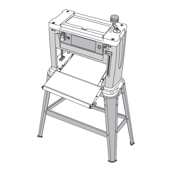
V. Know your thickness planer Cutter head depth adjustment handle Cutter head assembly Up/down direction decal Reset button Storage compartment ON/OFF switch Cutter head depth scale Carrying handle Motor brushes Rubber feet Measurement scale Support/out-feed roller Mounting holes Dust chute In-feed/out-feed roller extension knobs Work stand Support/in-feed roller... -
Page 11: Assembly And Adjustments
VI. Assembly and adjustments Unpacking (Fig. 1) Carefully unpack the thickness planer and all of its parts, and compare them against the list below. Do not discard the carton or any packaging until the thickness planer is completely assembled. WARNING: IF ANY PART IS MISSING OR DAMAGED, DO NOT PLUG THE THICKNESS PLANER IN UNTIL THE MISSING OR DAMAGED PART IS REPLACED AND ASSEMBLY IS COMPLETE. - Page 12 VI. Assembly and adjustments (continued) Assembly Fig. 2 Assembling the leg stand (Fig. 2) Use the screws, washers, and nuts supplied in the hardware kit to attach the pieces of the leg stand together. Do not tighten the hardware completely until the leg stand is assembled.
- Page 13 VI. Assembly and adjustments (continued) Install the cutter head handle (Fig. 4) Fig. 4 1. Place the cutter head handle (1) over the spindle on the top of the thickness planer. 2. Secure the handle using the hex screw and washer (2) provided.
-
Page 14: Operation
VII. Operation WARNING: IF YOU HAVE TO REMOVE A WORKPIECE FROM THE THICKNESS PLANER, MAKE SURE THE ON/OFF SWITCH IS IN THE OFF POSITION AND THE POWER CORD IS REMOVED FROM THE POWER SOURCE. ON/OFF Switch (Fig. 6) To turn the thickness planer on, insert the safety Fig. - Page 15 VII. Operation (continued) Getting started Before you start, check for loose fasteners or hardware. Make sure the cutter head knife guard is securely mounted and the cutter head rotates freely. With the power switch in the OFF position, lower the cutter head to about 1" (25.4 mm) to the table.
- Page 16 VII. Operation (continued) Planing operation The thickness planer will automatically feed the workpiece into and out of the cutter head. Do not force the planer to work faster that it is designed to work. Damage to the workpiece and the planer can result. Thickness planers work best if at least one side of the workpiece is flat.
- Page 17 VII. Operation (continued) Feeding the workpiece (Fig. 7 and 8) Fig. 7 Always feed the workpiece with the grain (1), if possible. If the workpiece must be fed against the grain (2), make very light cuts. Hold the workpiece down firmly along the workpiece guides and allow the planer to automatically feed the workpiece to the PL008...
- Page 18 VII. Operation (continued) Setting the planing depth (Fig. 9 – 11) Fig. 9 Establish the starting point before attempting to plane the surface. The depth of the cutter head contact with the workpiece should only be enough to brush the surface.
-
Page 19: Maintenance
VIII. Maintenance Replacing cutter head knives and cleaning WARNING: TURN THE POWER SWITCH TO THE OFF POSITION AND UNPLUG THE POWER CORD FROM THE POWER SOURCE BEFORE ADJUSTING, MAINTAINING, CLEANING, OR LUBRICATING THE THICKNESS PLANER. USE CARE WHEN HANDLING THE KNIVES. THE CUTTING EDGE CAN BE VERY SHARP. Change one knife at a time. - Page 20 VIII. Maintenance (continued) WARNING: TURN THE POWER SWITCH TO THE OFF POSITION AND UNPLUG THE POWER CORD FROM THE POWER SOURCE BEFORE ADJUSTING, MAINTAINING, CLEANING, OR LUBRICATING THE PLANER. USE CARE WHEN HANDLING THE KNIVES. THE CUTTING EDGE CAN BE VERY SHARP. Knife installation (Fig.
- Page 21 VIII. Maintenance (continued) Sharpening cutter head knives (Fig. 17) Fig. 17 The knives can be honed individually using an ordinary oilstone (1). Make sure the oilstone is not worn in the centre, it must be flat. Be sure to remove any burrs on the flat side.
- Page 22 VIII. Maintenance (continued) Storing (Fig. 19 and 20) Store the planer in a cool dry place. Clean and Fig. 19 lubricate prior to storage. Apply a light coat of oil to the knives in order to protect them from moisture. Be sure to clean the knives after storing.
-
Page 23: Replacement Parts
12 1/2" THICKNESS PLANER WITH WORK STAND 55-5503-4 ® Use only Mastercraft Thickness Planer replacement parts. Use of any other part may cause damage to the product. Any and all servicing of the thickness planer should be performed by a qualified service technician. - Page 24 IX. Replacement parts (continued) ® MASTERCRAFT 12 1/2" THICKNESS PLANER WITH WORK STAND 55-5503-4 WARNING: ANY ATTEMPT TO REPAIR OR REPLACE ELECTRICAL PARTS ON THIS TOOL MAY CREATE A HAZARD UNLESS REPAIRS ARE CARRIED OUT BY A QUALIFIED SERVICE TECHNICIAN.
- Page 25 IX. Replacement parts (continued) ® MASTERCRAFT 12 1/2" THICKNESS PLANER WITH WORK STAND 55-5503-4 Motor Assembly...
-
Page 26: Warranty
Rubber feet X. Warranty This Mastercraft product carries a three (3) year repair warranty against defects in workmanship and materials. At its discretion, Mastercraft Canada agrees to have any defective part(s) repaired or replaced free of charge, within the stated warranty period, when returned by the original purchaser with proof of purchase.
Need help?
Do you have a question about the 55-5503-4 and is the answer not in the manual?
Questions and answers
Need part 28 cone gears and Motor brushes for 55-5503-4 Mastercraft planer, where to buy replacement
Regarding a 12.5" planer. 55-5503-4. Is version 1 the same as version 2 model? I have an older (2013?2014?) model. I need to replace the sprocket gears (part #67) and wondered if the parts would be compatible. Can't get parts for version 1 but can get parts for version 2.