
Related Manuals for MasterCraft 55-5504-2


Summary of Contents for MasterCraft 55-5504-2
- Page 1 12 1/2" THICKNESS PLANER 55-5504-2 Operation and Safety Instructions Toll Free Hotline: 1-800-689-9928 Phone: (905) 792-9769 Fax: (905) 792-7670 310-9902-001 10/02...
-
Page 2: Table Of Contents
Warranty ............28 I. Technical data 12 1/2" THICKNESS PLANER MODEL NUMBER: 55-5504-2 MOTOR: 120 V, 60 Hz, 15 A MOTOR SPEED:... -
Page 3: General Safety Rules
II. General safety rules Safety is a combination of common sense, staying alert and knowing how your planer works. WARNING: TO AVOID MISTAKES THAT COULD CAUSE SERIOUS INJURY, DO NOT PLUG IN THE PLANER UNTIL THE FOLLOWING STEPS HAVE BEEN READ AND UNDERSTOOD. - Page 4 II. General safety rules ... continued II. General safety rules 14. NEVER STAND ON THE TOOL. Serious injury could result if the tool tips or is accidentally hit. DO NOT store anything above or near the tool. 15. DON’T OVERREACH. Keep proper footing and balance at all times. Wear oil-resistant rubber-soled footwear.
-
Page 5: Specific Safety Rules For The Planer
III. Specific safety instructions for the planer BEFORE USING THE PLANER WARNING: TO AVOID MISTAKES THAT COULD CAUSE SERIOUS, PERMANENT INJURY, DO NOT PLUG IN THE PLANER UNTIL THE FOLLOWING STEPS HAVE BEEN READ AND UNDERSTOOD. Your planer comes completely assembled. The only assembly required is the cutterhead depth adjustment handle. - Page 6 III. Specific safety instructions for the planer ... continued BEFORE EACH USE WARNING: THE PULLEYS AND THE MOTOR INCLUDED WITH THE PLANER WILL RUN THE CUTTERHEAD AT THE CORRECT OPERATING RPM. USE OF A DIFFERENT MOTOR OR PULLEYS WILL CHANGE SPEEDS AND COULD CAUSE JAMMING, DAMAGE, KICKBACK, THROWN BLADES OR OTHER DANGERS.
- Page 7 III. Specific safety instructions for the planer ... continued DRESS FOR SAFETY: • Plan ahead to protect your eyes, hands, face and ears. • Do not wear loose clothing, gloves, neckties or jewellery (rings, wrist watches). They can get caught and draw you into moving parts. •...
- Page 8 III. Specific safety instructions for the planer ... continued WHEN THE PLANER IS RUNNING WARNING: DO NOT ALLOW FAMILIARITY (GAINED FROM FREQUENT USE OF YOUR PLANER) TO CAUSE A CARELESS MISTAKE. REMEMBER THAT A CARELESS FRACTION OF A SECOND IS ENOUGH TO CAUSE A SEVERE INJURY. KEEP CHILDREN AWAY: •...
-
Page 9: Electrical Information
IV. Electrical information GROUNDING INSTRUCTIONS IN THE EVENT OF A MALFUNCTION OR BREAKDOWN, grounding provides the path of least resistance for electric current and reduces the risk of electric shock. This tool is equipped with an electric cord that has an equipment grounding conductor and a grounding plug. The plug MUST be plugged into a matching outlet that is properly installed and grounded in accordance with ALL local codes and ordinances. - Page 10 IV. Electrical information ... continued GUIDELINES FOR USING EXTENSION CORDS WARNING: THIS PLANER IS FOR INDOOR USE ONLY. DO NOT EXPOSE TO RAIN OR USE IN DAMP LOCATIONS. Make sure your extension cord is in good condition. When using an extension cord, be sure to use one heavy enough to carry the current your product will draw.
-
Page 11: Know Your Planer
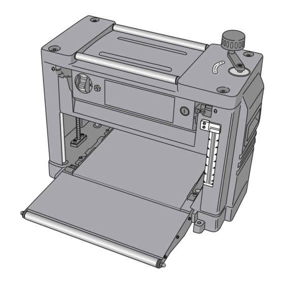
V. Know your planer PL002 1. Transport rollers 4. Workpiece guides 10. Cutterhead depth (used to transport 5. Support/infeed roller adjustment handle workpiece back to infeed 6. Mounting holes 11. UP/DOWN direction decal for next planing pass) 7. Measurement scale 12. -
Page 12: Assembly And Adjustments
VI. Assembly and adjustments Unpacking (Fig. 1) Carefully unpack the planer and all its parts, and compare it to the list below. Do not discard the carton or any packaging until the planer is completely assembled. WARNING: IF ANY PART IS MISSING OR DAMAGED, DO NOT PLUG IN THE PLANER UNTIL THE MISSING OR DAMAGED PART IS REPLACED. - Page 13 VI. Assembly and adjustments ... continued Power switch (Fig. 2) Fig. 2 To turn the planer ON, insert the switch key (1) into the slot. Move the switch toward the ON position. To turn the planer OFF, move the switch toward the OFF position.
- Page 14 VI. Assembly and adjustments ... continued VI. Assembly and adjustments Before starting Before you start, check for loose fasteners or hardware. Make sure the cutterhead knife guard is securely mounted and the cutterhead rotates freely. With the power switch in the OFF position, lower the cutterhead to about 1" (25.4 mm) to the table.
-
Page 15: Operation
VII. Operation Planing operation NOTE: The planer will feed the workpiece automatically to and from the cutterhead. Do not force the planer to work more than necessary. Damage to the workpiece and the planer can result. Planers work best if at least one side of the workpiece is flat. If both sides are rough, the planer should be used to create one flat side. - Page 16 VII. Operation ... continued Workpiece support Prevent sagging or snipes in the workpiece during planing. Support the workpiece by placing supports on both ends of the planer or install your planer at a depth where the planer meets your work bench. The supports must be at the same height of the planer or depth of installation must be at the same height as the planer.
- Page 17 VII. Operation ... continued Turn the power switch to the ON position. Fig. 9 Slowly guide the workpiece along the workpiece guides into the planer. If the cutterhead makes contact with the workpiece, back out the workpiece and raise the cutterhead UP using the cutterhead depth adjustment handle (2).
-
Page 18: Maintenance
VIII. Maintenance Replacing cutterhead knives and cleaning WARNING: TURN THE POWER SWITCH OFF AND REMOVE THE POWER CORD FROM THE POWER SOURCE BEFORE ADJUSTING, MAINTAINING, CLEANING OR LUBRICATING THE PLANER. USE CARE WHEN HANDLING THE KNIVES. THE CUTTING EDGE CAN BE VERY SHARP. NOTE: Change one knife at a time. - Page 19 VIII. Maintenance ... continued Knife installation (Fig. 14, 15) Fig. 14 Clean knives regularly. Gum and pitch collects on knives and causes excess friction during operation. Knives will overheat and wear. Remove knives to clean. Use a gum and pitch remover. Carefully place knife (6) back into the cutterhead (7).
- Page 20 VIII. Maintenance ... continued Carbon brush replacement (Fig. 17) Check the condition of the carbon brushes after 50 hours of use of your new planer. If the brushes are worn to 1/16" (2 mm) in length, replace them. Fig. 17 WARNING: BE SURE TO UNPLUG THE POWER CORD FROM THE POWER SOURCE BEFORE INSPECTING THE CARBON BRUSHES.
- Page 21 VIII. Maintenance ... continued Sharpening cutterhead knives (Fig. 18) Fig. 18 The knives can be honed individually with an ordinary oilstone (1). Make sure the oilstone is not worn in the centre, it must be flat. Be sure to remove any burrs on the flat side. If the blades are nicked, they must be replaced or reground.
-
Page 22: Replacement Parts
IX. Replacement parts MASTERCRAFT ® 12 1/2" THICKNESS PLANER 55-5504-2 When servicing your Mastercraft ® planer, use Mastercraft ® replacement parts only. Use of any other parts may cause product damage. Any and all servicing of the planer should be performed by a qualified service technician. - Page 23 IX. Replacement parts ... continued MASTERCRAFT ® 12 1/2" THICKNESS PLANER 55-5504-2 EXPLODED VIEW OF THE PLANER BODY (100 SERIES)
- Page 24 IX. Replacement parts ... continued MASTERCRAFT ® 12 1/2" THICKNESS PLANER 55-5504-2 PARTS LIST FOR THE PLANER MOTOR (200 SERIES) Description No. Description Motor housing Bearing Stator Cushion C-ring Screw M5x60 Bearing Logo label Sprocket wheel Bearing Dust guard Armature...
- Page 25 IX. Replacement parts ... continued MASTERCRAFT 12 1/2" THICKNESS PLANER 55-5504-2 ® EXPLODED VIEW OF THE PLANER MOTOR (200 SERIES)
- Page 26 IX. Replacement parts ... continued MASTERCRAFT ® 12 1/2" THICKNESS PLANER 55-5504-2 PARTS LIST OF THE PLANER BASE (300 SERIES) No. Description No. Description Threaded pole Spring pin Work table Cone-gear Screw C-ring Fence Column Screw Strain relief Threaded pole...
- Page 27 IX. Replacement parts ... continued MASTERCRAFT 12 1/2" THICKNESS PLANER 55-5504-2 ® EXPLODED VIEW OF THE PLANER BASE (300 SERIES)
-
Page 28: Warranty
X. Warranty This power tool is guaranteed for a period of three (3) years against defects in workmanship and materials. Should this power tool become defective within the stated warranty period, return it to the store with proof of purchase, and it will be replaced or repaired free of charge. This power tool is not guaranteed if used for industrial or commercial purposes.
Need help?
Do you have a question about the 55-5504-2 and is the answer not in the manual?
Questions and answers
Where would I get a reset button for my 55-5504-2 planer
The reset button for the MasterCraft 55-5504-2 planer is shown in Figure 3 of the manual. It is used in case of an overload.
This answer is automatically generated
Part number for 55-5504-2 Mastercraft 12 inch portable planer need blades
How much would it cost for one sprocket #137 and one chain#138 page 22
where can I order some parts for this model
details of the belt. Part no 26. Where to order? in Québec.