Advertisement
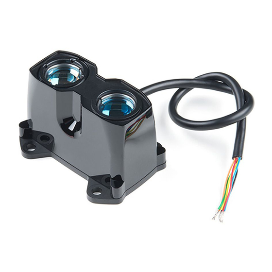
LIDAR-LITE V3HP
OPERATION MANUAL AND
TECHNICAL SPECIFICATIONS
Laser Safety
This device requires no regular maintenance. In the event that
the device becomes damaged or is inoperable, repair or service
must be handled by authorized, factory-trained technicians only.
Attempting to repair or service the unit on your own can result in
direct exposure to laser radiation and the risk of permanent eye
damage. For repair or service, contact your dealer or Garmin
for more information.
This device has a protective housing which, when in place,
prevents human access to laser radiation in excess of the
accessible emission limit (AEL) for Class 1 laser products. This
device should not be modified or operated without its housing or
optics. Operating this device without a housing and optics, or
operating this device with a modified housing or optics that
expose the laser source, may result in direct exposure to laser
radiation and the risk of permanent eye damage. Removal or
modification of the diffuser in front of the laser optic may result in
the risk of permanent eye damage.
This device emits laser radiation. Use of controls or adjustments
or performance of procedures other than those specified herein
may result in hazardous radiation exposure.
This laser product is designated Class 1 during all procedures of
operation. When the ranging feature of the device is activated, a
laser emitter of a ranging module may emit laser radiation and
the device should not be aimed toward anyone. Avoid looking
toward the laser emitter or into the laser radiation (beam) when
operating the device. It is advisable to turn off the ranging
module when it is not in use. This device must be used only
according to the directions and procedures described in this
documentation.
Do not leave this device within the reach of children.
CLASS 1 LASER PRODUCT
Classified EN/IEC 60825-1 2014
This product is in conformity with performance standards for
laser products under 21 CFR 1040, except with respect to those
characteristics authorized by a variance number.
Specifications
Specification
Size (L × W × H)
Weight
Operating temperature
Power
Current consumption
Range (70% reflective target)
April 2020
WARNING
CAUTION
NOTICE
Measurement
40.18 × 54.99 × 35 mm (1.58 ×
2.16 × 1.38 in.)
38 g (1.34 oz.)
-20 to 60°C (-4 to 140°F)
5 Vdc nominal
4.5 Vdc min., 5.5 Vdc max.
65 mA idle
85 mA during an acquisition
40 m (131 ft.)
Specification
Resolution
Accuracy < 2 m
Accuracy ≥ 2 m
Update rate (70% reflective target) Greater than 1 kHz typical
User interface
I2C interface
®
PWM interface
Water rating
NOTE: *The device withstands incidental exposure to water of
up to 1 m for up to 30 min. For more information, go to
www.garmin.com/waterrating.
Device Dimensions
GUID-1EAC1F92-654C-4E02-9B6D-0FDC7A0DB1BF v2
Measurement
±1 cm (0.4 in.)
±5 cm (2 in.) typical
NOTE: Nonlinearity present below
1 m (39.4 in.)
±2.5 cm (1 in.) typical
Mean ±1% of distance max
Ripple ±1% of distance max
Reduced sensitivity at high update
rates
I2C
PWM
External trigger
Fast-mode (400 kb/s)
Default 7-bit address 0x62
Internal register access and control
External trigger input
PWM output proportional to
distance at 10 microsecond/cm
IEC 60529 IPX7*
Important:
The bare wire portion of the
wiring harness is not water
resistant, and can act as a path
for water to enter the device. All
bare-wire connections must
either be made in a water-tight
location or properly sealed.
Water may enter under the
transmitting lens. This could
affect performance, but will not
affect the IEC 60529 IPX7
water rating.
Advertisement
Table of Contents

Subscribe to Our Youtube Channel
Related Manuals for Garmin LIDAR-LITE V3HP


Summary of Contents for Garmin LIDAR-LITE V3HP
- Page 1 I2C interface Fast-mode (400 kb/s) direct exposure to laser radiation and the risk of permanent eye Default 7-bit address 0x62 damage. For repair or service, contact your dealer or Garmin ® Internal register access and control for more information. PWM interface...
-
Page 2: Laser Specifications
Standard I2C Wiring 54.99 mm (2.16 in.) 36 mm (1.42 in.) 27.69 mm (1.09 in.) 16 mm (0.63 in.) Item Description Notes 32 mm (1.26 in.) 680microfarad You must observe the correct polarity 40.18 mm (1.58 in.) electrolytic capacitor when installing the capacitor. Power ground (-) Black wire 4 mm (0.16 in.) -
Page 3: Operational Information
Power ground (-) Black wire I2C wire to account for cable connection capacitance. Garmin recommends Mode control connection Yellow wire starting with 4.7 kiloohm resistors and adjusting if necessary. Monitor pin on Connect one side of the resistor to the... - Page 4 slave device, under the control of an I2C master device. It The maximum acquisition count limits the number of times the supports 400 kHz Fast Mode data transfer. device will integrate acquisitions to find a correlation record peak (from a returned signal), which occurs at long range or with low The I2C bus operates internally at 3.3 Vdc.
- Page 5 Arduino controller, and uses the term LIDAR device to refer to be written to or read from its shift register. the LIDAR-Lite v3HP device acting as a slave on the I2C bus. Data transmits over the serial bus in sequences of nine clock When working with the I2C serial bus protocol, the device pulses (eight data bits followed by an acknowledge bit).
- Page 6 The master requests a read operation from the LIDAR device After the read cycle is done, the master sends a stop or sends a write operation to the LIDAR device. condition to complete the operation. Read Operation Write Operation After the master establishes communication with the LIDAR After the master establishes communication with the LIDAR device, you can obtain a reading from the LIDAR device.
- Page 7 Bit Function Bit Function Signal overflow flag 7:0 Received signal strength calculated from the value of the highest peak in the correlation record and how many acquisitions were 0: Signal data has not overflowed performed. 1: Signal data in correlation record has reached the maximum value before overflow (occurs with a strong received signal strength) 0x0f...
- Page 8 0x1a 0x27 R/W Name Description Initial Value R/W Name Description Initial Value R/W I2C_SEC_ADDR Write new I2C address after unlock R/W PEAK STACK Registers read successive values LOW BYTE from the peak stack register. Data from the stack register is used for post Bit Function processing.
-
Page 9: Frequently Asked Questions
>1.5 • Retroreflective kHz with small acquisition count settings. Diffuse Reflective Surfaces You can find sample Arduino code for this in the Garmin GitHub Purely diffuse surfaces are found on materials that have a repository at https://github.com/garmin/LIDARLite_Arduino textured quality that causes reflected energy to disperse _Library. - Page 10 © 2018 Garmin Ltd. or its subsidiaries Garmin ® and the Garmin logo are trademarks of Garmin Ltd. or its subsidiaries, registered in the USA and other countries. Arduino ® is a registered trademark of Arduino AG. Arduino wiring diagrams were created using Fritzing.
Need help?
Do you have a question about the LIDAR-LITE V3HP and is the answer not in the manual?
Questions and answers