
Subscribe to Our Youtube Channel
Related Manuals for Elektrogas VMH DN Series


Summary of Contents for Elektrogas VMH DN Series
- Page 1 Safety shut off valves for gas with hydraulic actuator DN65 … DN300 delta-elektrogas.com EE175 - 0117...
-
Page 2: Table Of Contents
ELEKTROGAS – Technical Sheet EE175 - 0117 Contents Description ………………………………………….. 3 Features …………………………………………….. Functioning and application ………………………. Special versions and optionals …………………… Technical specifications …………………………… 5 Gas flow chart (pressure drop) …………………… Standards and approvals …………………………. Ordering information ………………………………. 10 Installation, adjustment and servicing ………….. -
Page 3: Description
ELEKTROGAS – Technical Sheet EE175 - 0117 Description The VMH type valve is a safety shut off valve for gas with hydraulic actuator. It is suitable for air or gas blocking and releasing controls, required in the main pipe of gas power burners,... -
Page 4: Functioning And Application
ELEKTROGAS – Technical Sheet EE175 - 0117 Functioning and application The VMH type valve is a safety shutting device using auxiliary power supply. When it is de-energized, the spring pushes on the seal disc, keeping the gas passage closed. In this condition the inlet chamber is filled with pressurized gas that forces on the disc, improving the seal. -
Page 5: Special Versions And Optionals
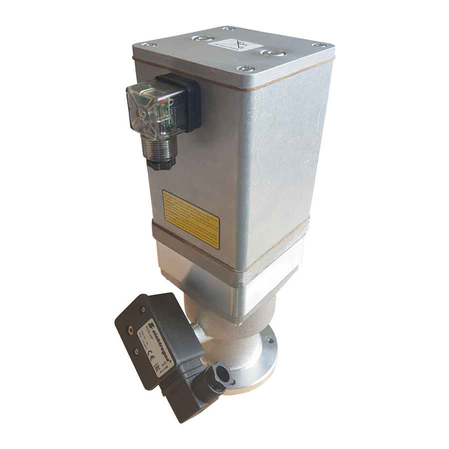
ELEKTROGAS – Technical Sheet EE175 - 0117 Special versions and optionals A switch can be installed as a closed position indicator (see PCS datasheet ). Whole range can be provided with Ex-proof execution for use in Zone 2, according to 94/9/EC Directive (ATEX). - Page 6 ELEKTROGAS – Technical Sheet EE175 - 0117 Fig. 3 Tab. 2 Flow Overall dimensions [mm] Opening Pmax Weight Max cycles Model Conn. time * per hour * [bar] [Kg] [sec] [m³/h] VMH7 * DN 65 10..15 83,0 4x18 VMH8 * DN 80 10..15...
- Page 7 ELEKTROGAS – Technical Sheet EE175 - 0117 Gas flow chart (Pressure drop) Fig. 4 Formula of conversion Tab. 3 Gas type Specific gravity from air to other gases ρ ρ [Kg/m³] ⋅ 1,25 1,00 Natural gas 0,80 1,25 Town gas...
- Page 8 ELEKTROGAS – Technical Sheet EE175 - 0117 When the flow read on the diagram is referred to operating pressure instead of standard conditions, the pressure drop ∆p read on the diagram must be multiplied for the factor: (1+ relative pressure in bar)
-
Page 9: Standards And Approvals
ELEKTROGAS – Technical Sheet EE175 - 0117 Standards and approvals The valves are designed and manufactured according to European Directive on Gas appliances 2009/142/EC and the certification has been issued by the notified body: Kiwa Nederland B.V. Wilmersdorf, 50 7300 AC Apeldoorn Reg-n°... -
Page 10: Ordering Information
ELEKTROGAS – Technical Sheet EE175 - 0117 Ordering Information Tab. 4 Valve type VMH Connections size and operative pressure 7 = DN65 1.6bar 8 = DN80 1.6bar 9 = DN100 1.3bar 93 = DN125 0.5bar 93U = DN125 1.3bar 95 = DN150 0.5bar 95U = DN150 1.3bar... -
Page 11: Installation, Adjustment And Servicing
ELEKTROGAS – Technical Sheet EE175 - 0117 Installation, adjustment and servicing To assure a proper and safe operation, as well as a long life of the valve, installation procedure and periodical servicing are very important topics and the following instructions should be always fulfilled. - Page 12 ELEKTROGAS – Technical Sheet EE175 - 0117 Check correct alignment of connecting pipes. Ensure that installing area is protected from rain and water splashes or drops. Remove the end caps and make sure no foreign body is entered into the valve during handling.
- Page 13 ELEKTROGAS – Technical Sheet EE175 - 0117 ELECTRICAL CONNECTION (IEC 730-1) - Using a screwdriver remove the plug from the actuator. - Unscrew the gland-nut (G) and remove the washer (F) and grommet (E). - To remove the terminal block (A)
- Page 14 ELEKTROGAS – Technical Sheet EE175 - 0117 Fig. 8 WARNING Adjustments below 40% of capacity are unadvisable because they may cause turbulence. PCS (closed position indicator switch) mounting All VMH valve can be equipped with PCSHP (closed position indicator switch for VMH actuator).
- Page 15 ELEKTROGAS – Technical Sheet EE175 - 0117 To maintain a good performance of the system, almost once a year, an external inspection of the valve is recommended. Due to seals aging, to ensure safe operation, we recommend valve replacement after 10 years from the date of manufacture stamped on the product.
- Page 16 ELEKTROGAS – Technical Sheet EE175 - 0117 ACTUATOR REPLACEMENT Before starting with actuator replacement, make sure it is the cause of failure. To replace the actuator do the following: Make sure an identical spare part is available. Switch off power supply and remove the plug (8).
Need help?
Do you have a question about the VMH DN Series and is the answer not in the manual?
Questions and answers