Table of Contents
Advertisement
Quick Links
Advertisement
Table of Contents

Related Manuals for LevelOne GEP-2841


Summary of Contents for LevelOne GEP-2841
- Page 1 Web Management Guide ( GEP-2841 )
-
Page 2: Product Introduction
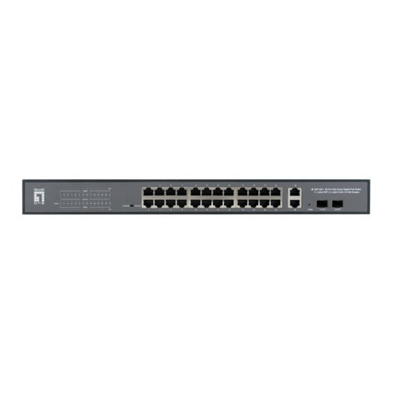
Chapter Ⅰ Product Introduction Product introduction The LevelOne GEP-2841 Web Smart Gigabit PoE Switch, provides 24 PoE ports 10/100/1000Base-T plus 2 port Gigabit Uplink SFP and 2 port Gigabit Uplink RJ45 to enable high speed network. With the plus the clearly visible status LEDs provide simple monitoring of port link activity. -
Page 3: List Of Accessories
Indicator Status Description Light on Power on ① Power Light off No power Light on PoE power in ② Light off PoE without power Light on The current operating rate is 1000Mbps ③ 1000M The current operating rate is 10 / Light off 100Mbps or the link is not connected Light on... -
Page 4: Power Plug
Figure 2-2" Power Plug 1. The power line of the switch adopts a single-phase three wire power socket, the middle pin is the grounding wire, the left pin is the zero wire, and the right pin is the live wire. Please check before operation. Figure 2-3 Connect the power cable 1. - Page 5 1. Check whether there is enough heat dissipation space around the switch and whether the air circulation is smooth# 2. Check whether the power supply of the power socket meets the specification of the switch# 3. Check that the power supply, switch, rack and other equipment are properly grounded#...
- Page 6 Chapter Ⅱ Login management interface Logging on to the equipment 1. Connect the RJ-45 interface cable of a switch with a computer using a network cable. 2. Set the TCP/IP properties of the computer, see the Appendix: Setting up yourcomputer. 3.
- Page 7 Chapter Ⅲ WEB Managed function Web details ① Interface status: displays the working status of the port. Green indicates that the port is connected, and unshaded indicates that the port is not connected" ② Function navigation tree: you can quickly switch to the corresponding function page through function navigation"...
-
Page 8: User Account
2. IP Setting Displays and sets the management IP address of the switch" When the IP mode is "static IP", you can manually configure IP address, subnet mask and gateway information" When the IP mode is "DHCP", the switch will automatically obtain IP information through the DHCP server in the network"... -
Page 9: Port Setting
4. Port Setting Figure 0-4 On the port setting page, the user sets and displays the port status, including the following contents! Alias: used to describe or comment on the port# Status: "on" and "disabled". If it is set to "disabled", the port will be closed manually and communication cannot be carried out# Speed / duplex: all interfaces are in "automatic"... -
Page 10: Static Vlan
Configuration VLAN 1. Static VLAN Figure 0-5 Static VLAN is used to set 802.1Q VLAN properties of switch ports" VLAN ID ! Identifier used to distinguish different VLANs. Terminals between different VLANs cannot communicate directly" VLAN ! The naming or description of the corresponding VLAN is usually used to intuitively distinguish the purposes of different VLANs"... -
Page 11: Port-Based Vlan
set all ports as the corresponding attributes)# Click the "add / modify" button below" Delete VLAN Check the delete selection box behind the corresponding VLAN ID in the VLAN list below, and click the "delete" button to delete the corresponding VLAN# VLAN 1 is the default VLAN and cannot be deleted. - Page 12 are planned to VLAN 10, 20 and 30 respectively" Figure 0-7 First, add corresponding VLAN and port settings on the static VLAN page. Take vlan10 as an example, fill in VLAN ID 10, select untagged under port 1, and tagged under port 24, and click Add.
- Page 13 Figure 0-9 For example: as shown in Figure 3-11, when it is necessary to access multiple broadband and the number of available physical interfaces of the router is insufficient, it is necessary to expand the WAN port through the switch (this function needs to be supported by the router function)"...
-
Page 14: Priority Selection
1. Priority selection Figure 0-11 The priority selection page sets different types of priorities for packets forwarded by the switch. The higher the value, the higher the priority" 2. Dscp remapping Figure 0-12 Set the DSCP value in the IP packet entering the switch port, and determine the output queue of the packet according to the DSCP value and priority configured by the user. -
Page 15: Port-Based Priority
the DSCP value and level priority value to be set to determine the output queue of data packets" 3. Priority to Queue Figure 0-13 The queue priority page is used to prioritize the packet queue output by the switch. The output queue of packets has been determined. -
Page 16: Packet Scheduling
5. Packet Scheduling On the queue scheduling page, you can select the scheduling policy and corresponding priority in the queue priority to define the weight value. (weight value min 1 max 15)" IGMP Setting Figure 0-15 After IGMP setting is enabled, the multicast message is only forwarded to the corresponding member port. -
Page 17: Port-Based Mirroring
Figure 0-16 Port-based Mirroring Figure 0-17 The port mirroring function can be set to copy the data in the specified direction of the port to the mirrored port. Up to 4 sets of port mirroring can be set" Direction ! RX refers to the data entering the port from the outside of the port, TX refers to the data sent from the port, and both is bidirectional"... -
Page 18: Port Isolation
Figure 0-18 As shown in Figure 3-20 below, Rx is selected for the direction (messages sent by the equipment connected to the switch are received for the switch port), 1 is selected for the mirror port, and 2 is selected for the mirrored port" Figure 0-19 Port Isolation Figure 0-20... - Page 19 Allow forwarding port ! The port that allows communication with the object port, that is, the port that is not mirrored and isolated from the object port. Except for the forwarding port, other ports cannot communicate with the object port" When adding ports, you can press and hold the mouse to drag and select multiple continuous ports.
-
Page 20: Bandwidth Control
port of all object ports to ensure normal communication with superior equipment" Bandwidth Control Figure 0-23 The bandwidth control function can limit the maximum rate of the specified port and direction, and the minimum control granularity is 16kbps" Port ! Set object port" Direction ! Receive or send direction"... -
Page 21: Mac Address
Security MAC Address 1. Static MAC Figure 0-25 The static MAC function can bind or block the specified MAC on the specified port and VLAN" MAC Address ! Controlled MAC address pair" VLAN ID ! Active VLAN ID (integer between 1-4094)" Port ! Active port (if not selected, it will take effect for all ports)"... -
Page 22: Storm Control
is connected to port 3 and VLAN 10, and can communicate normally when it is in other ports or VLANs" Figure 0-27 2. mac constraint Storm Control Figure 0-28 The storm control function can limit the packet rate of broadcast, multicast, unknown unicast and unknown multicast types on the specified port"... - Page 23 or off" Speed ! Maximum upper speed (in PPS, i.e. packets per second) DHCP Control Figure 0-29 The DHCP snooping function can eliminate the confusion of IP addresses caused by the manual configuration of IP addresses by illegal DHCP servers and clients" Example ! As shown in Figure 3-31, port 24 of the switch is connected to a router as a legal DHCP server.
- Page 24 Figure 0-31 At the same time, the IP address obtained by non DHCP method on the port selected as DHCP client will not be able to communicate" After the DHCP snooping function is configured, after the device on the port selected as DHCP client obtains the address for normal communication through the DHCP service, if the switch is restarted, the binding relationship will be invalid and communication will not be possible.
-
Page 25: Port Statistics
Monitoring Port Statistics Figure 0-32 Port Statistics status displays the management status, link status, and statistics of sending and receiving packets of the port. Click the "reset" button to reset the statistical information"... - Page 26 Tools HTTP Upgrade Figure 0-33 The firmware update page contains configuration export, import, and firmware upgrade functions" Export configuration ! Export the configuration on this switch for configuration backup" Import configuration ! Import the backed up configuration into the switch for configuration recovery"...
- Page 27 Save Figure 0-35 Save the changes made in the management page, and the unsaved configuration will be lost at the next restart! Restart Figure 0-36 Restart the switch"...
- Page 28 b) PoE Figure 0-37 This page can configure the POE function of the port and display the POE working status of the system and port" Select the port list ! The port selected below will be displayed in the list and used for setting the functions below"...
Need help?
Do you have a question about the GEP-2841 and is the answer not in the manual?
Questions and answers