Table of Contents
Advertisement
Advertisement
Table of Contents

Related Manuals for Mitsubishi Electric FREQROL-CS80


Summary of Contents for Mitsubishi Electric FREQROL-CS80
- Page 1 FACTORY AUTOMATION INVERTER FREQROL-CS80 COMP ACT & SMA R T...
- Page 2 Global Player GLOBAL IMPACT OF MITSUBISHI ELECTRIC Through Mitsubishi Electric’s vision, “Changes for the Better“ are possible for a brighter future. Mitsubishi Electric is involved in many areas including the following We bring together the best minds to Energy and Electric Systems create the best technologies.
- Page 3 Contents Features Example Connection Standard Specifications Outline Dimensions Terminal Connection Diagram, Terminal Specifications Explanation of the Control Panel and Parameter Unit FR Configurator2 Parameter List Protective Functions Option and Peripheral Devices Precautions for Operation/Selection, Precautions for Peripheral Device Selection Warranty...
- Page 4 Features Various Functions in a Small Body Compact and Smart Inverter World's smallest class Feature compact body In-house comparison Volume reduction to For the FR-CS84-012-60 <Conventional model> 128 mm (H) x 108 mm (W) x 129.5 mm (D) <CS80> 128 mm (H) x 68 mm (W) x 117.9 mm (D) Actual size of the FR-CS84-012-60 Space saving by the side-by-side installation Side-by-side installation is possible*.
- Page 5 115.2 kbps. good operability. Free trial version, which contains start-up functions, is Conventional model 38.4 kbps available. It can be downloaded at Mitsubishi Electric FA Global Website. CS80 115.2 kbps FR Configurator2...
- Page 6 Features Feature Easy maintenance Reduced wiring check time The wiring can be checked only by lifting the control terminal cover, which makes maintenance work easier. Easy wiring to the control circuit Spring clamp terminals (control circuit terminals) Spring clamp terminals* provide high reliability and easy wiring.
- Page 7 Features Lineup F R - C S 8 4 - 0 8 0 - 6 0 Circuit board coating Symbol Voltage class Symbol Power supply Symbol Description Symbol (conforming to IEC 60721-3-3 3C2/3S2) 200 V class None Three-phase 012 to 295 Inverter rated current (A) With 400 V class...
- Page 8 Features Variety of Functions to Support Various Applications Spinning Traverse function Power failure time decelerationto-stop function The traverse function, used for the traverse axis of spinning machine, The motor decelerates to a stop without prevents uneven winding or collapsing. coasting when power failure or undervolt- age occurs.
- Page 9 Features Fountain General-purpose magnetic Multi-speed function (Up to flux vector control 15-speed switching operation) Brake unit connection Operation speeds can be pre-set via parameters. Motor speed to meet the height requirements of A variety of fountain displays are possible by the fountain can be set and easily changed.
- Page 10 Example Connection AC power supply Must be within the permissible power supply specifications of the inverter. Enclosure surface Liquid crystal display operation panel operation panel Molded case circuit breaker (FR-PA07) (FR-LU08) Personal computer (MCCB), earth leakage circuit By connecting the connection cable Parameter unit breaker (ELB), or fuse (FR Configurator2)
- Page 11 Natural. Forced air. Approx. mass (kg) ∗1 The applicable motor capacity indicated is the maximum capacity applicable for use of the Mitsubishi Electric 4-pole standard motor. ∗2 The rated output capacity at an output voltage of 440 V. ∗3 When using the inverter in a surrounding air temperature of 50°C, the rated current is decreased to the value shown in the parentheses.
- Page 12 Common specifications Soft-PWM control, high carrier frequency PWM control (selectable among V/F control, General-purpose magnetic flux Control method vector control, Optimum excitation control). Output frequency range 0.2 to 400 Hz. 0.06/60 Hz at 0 to 10 V / 10 bits (terminals 2 and 4). Frequency Analog input 0.12/60 Hz at 0 to 5 V / 9 bits (terminals 2 and 4).
- Page 13 Outline Dimensions FR-CS84-012, 022 FR-CS84-036, 050, 080, 120, 160, 230, 295 FR-CS82S-025, 042 FR-CS82S-070, 100 φC 2×φC (Unit: mm) Three-phase 400 V class. Inverter model FR-CS84-012 FR-CS84-022 FR-CS84-036 FR-CS84-050 FR-CS84-080 FR-CS84-120 197.5 185.5 FR-CS84-160 FR-CS84-230 FR-CS84-295 Single-phase 200 V class. Inverter model FR-CS82S-025 FR-CS82S-042...
- Page 14 Terminal connection diagram Source logic Main circuit terminal Control circuit terminal Single-phase power input Brake unit MCCB (Option) Single-phase R/L1 AC power S/L2 supply MCCB Motor R/L1 Three-phase Inrush current S/L2 AC power limit circuit T/L3 supply Earth (Ground) Main circuit Earth (Ground) Control circuit...
- Page 15 Terminal Specifications Terminal names and terminal functions are those of the factory set. Terminal Type Terminal name Description symbol R/L1, S/L2, T/L3 AC power input Connect these terminals to the commercial power supply. U, V, W Inverter output Connect a three-phase squirrel-cage motor to these terminals. Connect the brake unit (FR-BU2), power regeneration common converter (FR-CV), or high power P/+, N/- Brake unit connection...
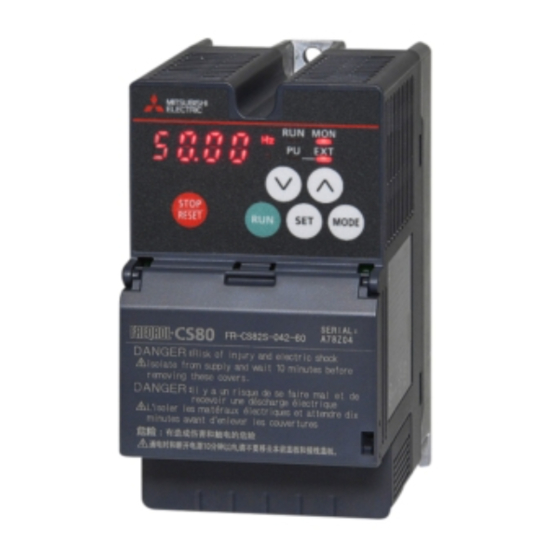
- Page 16 Explanation of the Operation Panel Components of the operation panel Appearance Name Description PU: ON when the inverter runs in the PU operation mode. EXT: ON when the inverter runs in the External operation mode. (ON when the inverter in the initial Inverter operation mode setting is powered ON.) LED indicator...
- Page 17 Basic operation Output frequency monitor Output current monitor Output voltage monitor (At power-ON) (Example) (Example) (Example) Blinking Blinking Blinking Fault history Fault history 1 Fault history 2 Fault history 8 External operation mode (At power-ON ) PU operation mode PU Jog operation mode Pressing the Pressing the SET key while in any of the screens...
- Page 18 FR-LU08 LCD Operation Panel • The FR-LU08 is an optional operation panel adopting an LCD panel capable of displaying text and menus. • Installation of the FR-LU08 on the enclosure surface is possible when using an optional parameter unit connection cable (FR-CB2[ ]). (To connect the (FR-LU08), an optional operation panel connection connector (FR-ADP) is required.) •...
- Page 19 Parameter unit (FR-PU07) • The parameter unit is an optional unit which has a ten-key direct input keypad, operating status display, and help function to make Description setting the inverter more convenient. Use for parameter setting The parameter unit connection cable FR-CB20[] is required to Press to choose the parameter setting mode.
- Page 20 INVERTER SETUP SOFTWARE (FR Configurator2) Inverter setup software is optional software in which anything from setup to maintenance can be easily carried out via a personal computer. Intuitive user interface Connected inverters are displayed in tree Tree view Tab change view format.
- Page 21 Parameter list Parameter list (by parameter number) For simple variable-speed operation of the inverter, the initial values of the parameters may be used as they are. Set the necessary parameters to meet the load and operational specifications. Parameter setting, change, and check can be made on the operation panel. NOTE •...
- Page 22 Minimum Initial Customer Function Name Setting range setting group value setting increment ∗2 F020 Second acceleration/deceleration time 0 to 3600 s 0.1 s 10 s ∗2 15 s ∗2 F021 Second deceleration time 0 to 3600 s, 9999 0.1 s 9999 A702 Restart coasting time...
- Page 23 Minimum Initial Customer Function Name Setting range setting group value setting increment Frequency setting / key lock operation — E200 0, 1, 10, 11 selection A710 Stall prevention operation level for restart 0 to 200% 0.1% 150% M464 Output current detection operation selection 0, 1 E000 —...
- Page 24 Minimum Initial Customer Function Name Setting range setting group value setting increment A300 Traverse function selection 0 to 2 A301 Maximum amplitude amount 0 to 25% 0.1% Amplitude compensation amount during A302 0 to 50% 0.1% deceleration Amplitude compensation amount during A303 0 to 50% 0.1%...
- Page 25 Changing the parameter setting value on the operation panel Changing the setting of Pr.1 Maximum frequency. Example Turning ON the power of the inverter The operation panel will be in monitor mode. Changing the operation mode Press to change the operation mode. Press to choose the PU operation mode.
- Page 26 Protective Functions List of fault indications If the displayed message does not correspond to any of the following or if you have any other problem, contact your sales representative. Error message Fault • Operation and setting faults are displayed on the operation panel •...
- Page 27 Reset method for the protective functions Reset the inverter by performing any of the following operations. Note that the accumulated heat value of the electronic thermal relay function and the number of retries are cleared (erased) by resetting the inverter. The inverter recovers about 1 second after the reset is released.
- Page 28 Option and Peripheral Devices Option List Name Model Applications, Specifications, etc. Applicable Inverter Liquid crystal display operation FR-LU08 Graphical operation panel with liquid crystal display All capacities ∗1 panel Parameter unit (8 languages) FR-PU07 Interactive parameter unit with LCD display All capacities Enclosure surface operation This operation panel enables inverter operation and monitoring of...
- Page 29 Name (Model) Specifications, Structure, etc. ● Attachment to enable installation of FR-CS80 series on DIN rail. ●Selection table Inverter Capacity Attachment Model FR-CS84 FR-CS82S FR-UDA01 012, 022 025, 042 FR-UDA02 036, 050, 080 070, 100 ● Approximate dimension FR-UDA01 FR-UDA02 DIN rail mounting attachments FR-UDA[]...
- Page 30 MCCB Install one MCCB per inverter. For the use in the United States or Canada, provide the appropriate UL and cUL listed fuse that is suitable for branch circuit protection. (Refer to the FREQROL-CS80 Instructions and Cautions for MCCB Use of Inverters.) ...
- Page 31 Selecting the rated sensitivity current for the earth leakage circuit breaker When using an earth leakage circuit breaker with the inverter circuit, Example select its rated sensitivity current as follows, independently of the 5.5mm ×5m 5.5mm ×50m PWM carrier frequency. Noise •...
- Page 32 Precautions for Operation/Selection Precautions for use of the inverter Installation • Install the inverter in a clean place with no floating oil mist, cotton Safety Precautions fly, dust and dirt, etc. Alternatively, install the inverter inside the "sealed type"...
- Page 33 When installing a molded case circuit breaker on the inverter output capacitive filter.) ∗1 side, contact the manufacturer of each product for selection. Mitsubishi Electric capacitive filter: FR-BIF, SF[], FR-E5NF-[], FR- S5NFSA[] ∗2 Recommended common mode choke: FT-3KM F series ...
- Page 34 Line-to-line leakage current Earth (ground) Type Influence and countermeasure When the inverter is run in the low acoustic noise mode, more leakage currents occur than in the non-low acoustic noise mode due • This leakage current flows via a static capacitance between the inverter output cables.
- Page 35 In some of three cases, however, Mitsubishi Electric Corporation may consider the possibility of an application, provided that the customer notifies Mitsubishi Electric Corporation of the intention, the application is clearly defined...
- Page 38 This solution solves customers' issues and concerns by enabling visualization and analysis that lead to improvements and increase availability at production sites. Utilizing our FA and IT technologies and collaborating with e-F@ctory Alliance partners, we reduce the total cost across the entire supply chain and engineeringchain, and support the improvement initiatives and one-step-ahead manufacturing of our customers.
- Page 39 YOUR SOLUTION PARTNER Low voltage: MCCB, MCB, ACB Medium voltage: VCB, VCC Power monitoring, energy management Mitsubishi Electric offers a wide range of automation equipment from PLCs and HMIs to CNC and EDM machines. Compact and Modular Controllers A NAME TO TRUST...
- Page 40 Mitsubishi Electric Corporation Nagoya Works is a factory certified for ISO14001 (standards for environmental management systems)and ISO9001(standards for quality assurance management systems) HEAD OFFICE: TOKYO BLDG., 2-7-3, MARUNOUCHI, CHIYODA-KU, TOKYO 100-8310, JAPAN L(NA)06113ENG-A(1711)MEE...
Need help?
Do you have a question about the FREQROL-CS80 and is the answer not in the manual?
Questions and answers