
Related Manuals for Galletti MCA Series


Summary of Contents for Galletti MCA Series
- Page 1 water chillers and heat pumps technical manual E U R O V E N T CERTIFIED PERFORMANCE...
-
Page 2: Declaration Of Conformity
MODELS AND CONFIGURATIONS ..........5 configurations, which make the MCA series an ideal solution for speeding up TECHNICAL FEATURES ............. 6 installation on the building site. Only top quality components are used for the 5.1 Rated tecnical data cooling mode .......... -
Page 3: Constructive Features
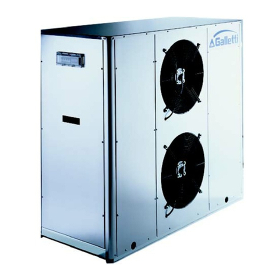
CONSTRUCTIVE FEATURES REFRIGERANT CIRCUIT VENTILATION SECTION - scroll compressor fitted in a sound proofed compartment. The units is including axial - type fans with airfoil - shaped blades, statically - inox braze - welded plate heat exchangers. and dynamically balanced on two levels provided with a protective outlet - finned block condenser coil with copper pipping and aluminium fins. - Page 4 COMPONENTS LAY-OUT MCA 25 - 30 - 37 Description R407C-air heat-exchangers R407C-water heat-exchanger Water differential pressure switch (fan housing) Air purge valve (fan housing) Expansion vessel (fan housing) Water tank (fan housing) R407C safety valve 4-way valve (MCA H) Thermostatic valve Automatic filling device Water safety valve Liquid receiver...
-
Page 5: Models And Configurations
MODELS AND CONFIGURATIONS The water chiller and heat pump of the MCA series are units that can be configured in order to meet the number of possible installation requirements. To simplify the order, Galletti proposes 3 different solutions with integrated hydronic kit, both in the cooling only and heat pump versions: WATER CHILLER MCA..CB... -
Page 6: Technical Features
TECHNICAL FEATURES COOLING ONLY RATINGS MCA-C 10 M Power supply V - ph - Hz 230-1-50 400-3-50 Cooling capacity 9,62 9,64 11,22 13,68 16,61 20,11 23,80 32,13 35,30 49,70 60,10 MCA CB Total power input 8,45 10,00 4,09 3,99 5,04 5,70 6,76 12,62... - Page 7 TECHNICAL FEATURES HEAT PUMPS RATINGS MCA-H 10 M Power supply 400-3-50 V - ph - Hz 230-1-50 Cooling capacity 30,95 33,90 9,25 9,28 10,77 13,18 16,49 19,30 22,86 48,20 58,30 MCA HB Cooling power input 12,94 4,20 4,09 5,15 5,84 6,93 8,67 10,26...
- Page 8 PERFORMANCES COOLING CAPACITIES MCA-C Inlet air dry bulbe temperature Tw in/out Inlet/outlet air temperature Cooling capacity Total electric absorbed power models with hydraulic kit (MCA-CP / MCA-CS) Tw in Tw out [°C] [°C] 10,1 3,62 9,47 4,00 8,79 4,45 8,07 4,95 7,31 5,51...
- Page 9 PERFORMANCES COOLING CAPACITIES MCA-C Inlet air dry bulbe temperature Tw in/out Inlet/outlet air temperature Cooling capacity Total electric absorbed power models with hydraulic kit (MCA-CP / MCA-CS) Tw in Tw out [°C] [°C] 21,4 7,10 20,0 7,89 18,4 8,78 16,8 9,76 15,0 10,8...
- Page 10 PERFORMANCES COOLING CAPACITIES MCA-H Inlet air dry bulbe temperature Tw in/out Inlet/outlet air temperature Cooling capacity Total electric absorbed power models with hydraulic kit (MCA-HP / MCA-HS) Tw in Tw out [°C] [°C] 9,77 3,70 9,14 4,10 8,46 4,56 7,74 5,07 6,98 5,64...
- Page 11 PERFORMANCES COOLING CAPACITIES MCA-H Inlet air dry bulbe temperature Tw in/out Inlet/outlet air temperature Cooling capacity Total electric absorbed power models with hydraulic kit (MCA-HP / MCA-HS) Tw in Tw out [°C] [°C] 20,7 7,27 19,2 8,08 17,7 8,99 16,1 10,0 14,3 11,1...
- Page 12 PERFORMANCES HEATING CAPACITIES MCA-H Inlet air dry bulbe temperature Tw in/out Inlet/outlet air temperature Heating capacity Total electric absorbed power models with hydraulic kit (MCA-HP / MCA-HS) Relative umidity In the heat pump operation (heating mode), the actual heating capacities of units may be lower than the values shown in the table, due to defrosting cycles.
- Page 13 PERFORMANCES HEATING CAPACITIES MCA-H Inlet air dry bulbe temperature Tw in/out Inlet/outlet air temperature Heating capacity Total electric absorbed power models with hydraulic kit (MCA-HP / MCA-HS) Relative umidity In the heat pump operation (heating mode), the actual heating capacities of units may be lower than the values shown in the table, due to defrosting cycles.
-
Page 14: Operating Limits
OPERATING LIMITS HEAT RECOVERY OPTIONS Supply voltage: ± 10% of rated voltage. In air-conditioning applications it is useful and often indispensable to have The operating limits shown in the diagrams are valid for thermal differentials heat available for heating sanitary water or controlling post-heating in air- of water between 3 and 8°C handling units where independent temperature and humidity control is Legend:... - Page 15 PRESSURE DROP ON WATER SIDE The following diagrams show evaporator pressure drops (∆pw) according to water flow rate (Qw) with average water temperature of 10°C. MCA 12 - 14 MCA 10 MCA 21 MCA 16 (kPa) Qw (l/s) MCA 30 MCA 25 MCA 50 MCA 37...
- Page 16 AVAILABLE UNIT PRESSURE HEAD The following diagrams show availiable unit pressure head (Pu) according to water flow rate (Qw) with average water temperature of 10°C. MCA 10 MCA 12 - 14 MCA 21 (kPa) MCA 16 Qw (l/s) (kPa) MCA 37 MCA 60 MCA 25 MCA 30...
-
Page 17: Water Circuit
WATER CIRCUIT When setting up the water circuit of the unit, it is advisable to follow the It is of fundamental importance that the incoming water supply is hooked up directions below and in any case comply with local or national regulations. to the connection marked "Water Inlet"... -
Page 18: Electrical Data
ELECTRICAL DATA 10 M Maximum power input 10,7 12,9 16,8 19,0 26,0 34,0 Maximum current absorption 28,4 12,4 14,4 16,1 18,4 21,4 28,0 33,0 37,2 44,0 49,0 Starting absorbed current 117,4 54,4 69,9 78,4 102,4 134,4 138,0 143,0 183,0 190,0 240,0 Fan motor rated power 0,16... - Page 19 OVERALL DIMENSIONS MCA 10 - 12 - 14 Legend: Water IN 1" female Water OUT 1" female Safety valve discharge outlet " Water supply " female Drain manifold " Power supply Φ 28 mm Electric control board Dampers fastening points 1143,5 1121 PA - BASE VIBRATION DAMPER KIT...
- Page 20 OVERALL DIMENSIONS MCA 16 - 21 Legend: Water IN 1" female Water OUT 1" female Safety valve discharge outlet " Water supply " female Drain manifold " Power supply Φ 28 mm Electric control board Dampers fastening points 1423,5 1401 210,5 210,5 184,5...
- Page 21 OVERALL DIMENSIONS MCA 25 - 30 - 37 Legend: Water IN 1" female Water OUT 1" female Safety valve discharge outlet " Water supply " female Drain manifold " Power supply Φ 28 mm Electric control board Dampers fastening points 1523 1500 1050...
- Page 22 OVERALL DIMENSIONS MCA 50 - 60 Legend: Water IN 2" female Water OUT 2" female Safety valve discharge outlet " Water supply " female Drain manifold " Power supply Φ 37 mm Electric control board Dampers fastening points 1989 1202 1966 1164 PA - BASE VIBRATION DAMPER KIT...
-
Page 23: Installation Clearance Requirements
INSTALLATION CLEARANCE REQUIREMENTS To guarantee the proper functioning of the unit and access for maintenance purposes, it is necessary to comply with the minimum installation clearance requirements shown in figures 1 and 2. Verify that there are no obstacoles in front of the fans air outlet. Avoid any and all situations of backflow of hot air between air outlet and inlet of the unit. - Page 24 40010 Bentivoglio (BO) Via Romagnoli, 12/a Tel. 051/8908111 Fax 051/8908122 www.galletti.it...
Need help?
Do you have a question about the MCA Series and is the answer not in the manual?
Questions and answers