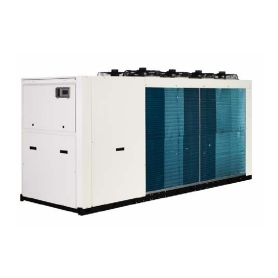
Galletti LCX Series User Manual
Cooling-only, heat pump and free-cooling versions
Hide thumbs
Also See for LCX Series:

Related Manuals for Galletti LCX Series


Summary of Contents for Galletti LCX Series
- Page 1 Installation, use and maintenance manual COOLING-ONLY, HEAT PUMP AND FREE-COOLING VERSIONS USER MANUAL...
- Page 2 For further information or communication, please contact the company at: info@galletti.it To find out the weight of each unit, please refer to the table in the paragraph “Rated specifications” RG66010687_rev.00...
-
Page 3: Table Of Contents
CONTENTS PAGE THE SERIES FIELD OF APPLICATION GENERAL INFORMATION INSPECTION, CONVEYANCE, SITING INSPECTION LIFTING AND CONVEYANCE UNPACKING SITING INSTALLATION INSTALLATION CLEARANCE REQUIREMENTS GENERAL GUIDELINES FOR PLUMBING CONNECTIONS WATER CONNECTION TO THE EVAPORATOR PROCEDURE FOR FILLING THE TANK SAFETY DEVICES ON THE HIGH-PRESSURE SIDE ELECTRICAL CONNECTIONS GENERAL INFORMATION FLOW SWITCH ON THE WATER SIDE... - Page 4 SERVICE THERMOSTAT ANTIFREEZE THERMOSTAT ANTI-RECYCLE TIMER OIL DIFFERENTIAL PRESSURE SWITCH 10 ROUTINE MAINTENANCE AND CHECKS 10.1 WARNINGS 10.2 GENERAL INFORMATION 10.3 REPAIRING THE COOLING CIRCUIT 10.4 TIGHTNESS TEST 10.5 HARD VACUUM AND DRYING OF THE COOLING CIRCUIT 10.6 CHARGING WITH R410A REFRIGERANT 10.7 ENVIRONMENTAL PROTECTION 11 DECOMMISSIONING THE UNIT 12 TROUBLESHOOTING...
- Page 5 Declaration of conformity The declaration of conformity is enclosed as a separate document with the papers supplied with the machine, usually placed inside the electric control board. RG66010687_rev.00...
-
Page 6: The Series
1 THE SERIES COOLING-ONLY and HEAT PUMP Fluid chillers and heat pumps designed to cool water or mixtures of water and an antifreeze agent, intended for civil air-conditioning and industrial cooling systems. LCX chillers, available in versions with different acoustic designs (“S”, “L”, “Q”) and cooling circuit architectures (Efficiency pack 1, 2 , 4), they cover a range of cooling capacities from 44.4 to 355 kW, calculated with reference to standard test conditions of water 12°/7°... - Page 7 Below is a list of all possible models, broken down by efficiency pack : Indicative cooling capacity of the efficiency pack 1 efficiency pack 2 efficiency pack 4 “cooling-only” version [kW] LCX042CL/CQ LCX042HL/HQ LCX052CL/CQ LCX052HL/HQ LCX062CS/CL/CQ LCX062HS/HL/HQ LCX072CS/CL/CQ LCX072HS/HL/HQ LCX082CS/CL/CQ LCX082HS/HL/HQ LCX091CS/CL/CQ LCX092CS/CL/CQ...
-
Page 8: Field Of Application
Chiller Configurations E.P. Std. Versions Efficiency Pack E.P. Noise Below is a list of all possible models, broken down by efficiency pack: Indicative cooling capacity of the efficiency pack 1 efficiency pack 4 “cooling-only” version [kW] LCX041FS/FL LCX051FS/FL LCX061FS/FL LCX071FS/FL LCX081FS/FL LCX091FS/FL LCX101FS/FL... - Page 9 Therefore only qualified personnel may perform any kind of work on the unit. THE UNIT MUST BE STARTED UP FOR THE FIRST TIME EXCLUSIVELY BY QUALIFIED PERSONNEL AUTHORISED BY GALLETTI S.P.A. (SEE ANNEX). AILURE TO COMPLY WITH THE RULES PROVIDED IN THIS MANUAL OR ANY MODIFICATION MADE...
-
Page 10: Inspection, Conveyance, Siting
4 INSPECTION, CONVEYANCE, SITING INSPECTION Upon receiving the unit, check that it is perfectly intact: the chiller left the factory in perfect conditions; immediately report any signs of damage to the carrier and note them on the Delivery Slip before signing it. -
Page 11: Unpacking
- possible reverberation of sound waves. All models belonging to the LCX series are designed and built for outdoor installation: avoid covering them with roof structures or positioning them near plants (even if they only partly cover the unit) which may interfere with the regular ventilation of the unit condenser. -
Page 12: Installation
5 INSTALLATION INSTALLATION CLEARANCE REQUIREMENTS It is of fundamental importance to ensure an adequate volume of air both on the intake and outlet sides of the finned condenser coils; it is highly important to prevent the air delivered from being re-aspirated as this may impair the performance of the unit or even cause an interruption of normal operation. -
Page 13: General Guidelines For Plumbing Connections
GENERAL GUIDELINES FOR PLUMBING CONNECTIONS When you are getting ready to set up the water circuit for the evaporator you should follow the directions below and in any case make sure you comply with national or local regulations (use the diagrams included in this manual as your reference). - Page 14 discharge cock and, where needed, drain tank in order to empty the system for maintenance or seasonal stops. [A 1” drainage valve is provided on the optional water buffer tank: this operation may only be carried out when the unit is disconnected from the power supply]. ...
-
Page 15: Water Connection To The Evaporator
WATER CONNECTION TO THE EVAPORATOR It is extremely important that the water inlet corresponds with the connection marked with the writing “Water Inlet”. Otherwise the evaporator would be exposed to the risk of freezing since the antifreeze thermostat would not be able to perform its function; moreover the reverse cycle would not be activated in the cooling mode, resulting in additional risks of malfunctioning. -
Page 16: Procedure For Filling The Tank
A standard feature of the LCX units is a device for controlling the flow rate (differential pressure switch) in the water circuit in the immediate vicinity of the evaporator. Any tampering with said device will immediately invalidate the warranty. It is advisable to install a metal mesh filter with mesh no large than 1mm on the inlet water pipe. -
Page 17: Safety Devices On The High-Pressure Side
SAFETY DEVICES ON THE HIGH-PRESSURE SIDE Cooling circuit safety devices are provided on each refrigerant circuit according to the volumetric capacity of the compressors installed, as prescribed by Directive 97/23 (PED); in particular, with respect to equipment design, this Directive requires manufacturers to abide by the technical standard nearest to the type of object produced;... -
Page 18: Flow Switch On The Water Side
The above operating conditions must always be complied with: failure to ensure said conditions will result in the immediate invalidation of the warranty. The electrical connections must be made in accordance with the information shown in the wiring diagram provided with the unit and current regulations. Electrical connections and preliminary checks: ... -
Page 19: Remote Controls
REMOTE CONTROLS If you wish to include a remote control for switching the unit on and off, you must remove the jumper between the contacts indicated in the wiring diagram and connect the remote ON/OFF control to the terminals themselves [see annexed wiring diagram]. All remote controls work with a very low voltage (24 Vac) supplied by the insulating transformer on the electrical control board. - Page 20 (available on all versions) RG66010687_rev.00...
-
Page 21: Start-Up
7 START-UP PRELIMINARY CHECKS Check that all the valves in the cooling circuit are open (liquid line). Check that the electrical connections have been made properly and that all the terminals are securely tightened. This check should also be included in a periodic six-month inspection. Check that the voltage at the RST terminals is 400 V ±... -
Page 22: Starting Operations
The diagram above illustrates a specific property [Charles’ Law] of gases, which are more soluble in liquids as the pressure increases but less soluble as the temperature increases: if the oil is held at a constant pressure, an increase in temperature will significantly reduce the amount of refrigerant dissolved in it, thus ensuring that the lubricating function desired is maintained. -
Page 23: Checks During Operation
CHECKS DURING OPERATION - Check the phase sequence relay on the control board to verify whether the phases occur in the correct sequence: if they do not, disconnect the unit from power supply and reverse two phases at the unit input. -
Page 24: Expansion Valve
Attention: the refrigerant R410A requires “POE” polyolester oil of a type approved by the compressor manufacturer. For no reason should a mineral oil be introduced into the oil circuit. Compressor Average T discharge (T1+T2)/2 real P T1 (start of condensation) DEW POINT T2 (end of condensation) BUBBLE POINT... -
Page 25: Stopping The Unit
Proactive action of an Electronic Expansion Valve: In the event of a compressor on/off request: The electronic driver pre-positions the valve at a point very near the final equilibrium point. A status of equilibrium is quickly reached with small adjustments. ... - Page 26 produced water 13° 10° 5° T outside -18° 42° 44° The lower limit is due to the limit of freezing temperature of glycol solutions with 35% of their weight made of glycol, the maximum admitted by the tightness of the pumps used. Minimum temperature of produced water °C 10 %...
- Page 27 The hydraulic circuit - Free-Cooling versions In addition to what has be mentioned above, the Free-Cooling versions foresee a 3-way valve capable of deviating the flow towards the Free-Cooling coils placed upstream the condensing coils, in the air flow direction. Valve activation is controlled by the microprocessor (ADVANCED as per standard) assessing the difference between the system return water (T1) set point T and the outside air (T2).
- Page 28 Free-cooling execution provides excellent energy savings in all those situations in which the outside temperature is lower than the fluid in circulation (process industry, close control applications, information technology in general, convention halls, etc.). The performance of the free-cooling circuit depends on the difference between the outside air T and that of the water circulating, as shown in the figure (fig.
-
Page 29: Water Flow To Evaporator
The units are designed and built to work with outdoor air temperatures ranging from -10 (with condensation control) to 45 °C: applications outside the specified limits may be authorised by Galletti S.p.A. subject to verification and subsequent authorisation in writing. On request, the units may be equipped with an electric heating element to heat up the evaporator in cases where the unit is exposed to severe temperatures during wintertime shutdown periods. - Page 30 Many of the functioning parameters and calibrations of the control systems are set by the microprocessor control and are protected by passwords. TABLE I - SETTING OF CONTROL DEVICES - LCX C SERIES CONTROL DEVICE SET POINT DIFFERENTIAL Service thermostat [CS-CL-CQ] °C - LCX H SERIES CONTROL DEVICE...
- Page 31 TABLE II – SETTING OF SAFETY AND CONTROL DEVICES - LCX C-H SERIES CONTROL DEVICE ACTIVATION DIFFERENTIAL RESETTING Antifreeze thermostat °C Automatic Maximum safety pressure switch -13.5 Manual Maximum safety pressure switch 40.5 -12.2 Manual Low pressure safety valve Minimum pressure switch +1.0 Automatic Modulating condensation control...
-
Page 32: Maximum Pressure Switch
MAXIMUM PRESSURE SWITCH The high pressure switch is of the manually reset type and classifiable as category 4 in accordance with the EEC 97/23 directive. It directly stops the compressor when the discharge pressure exceeds the set value (see section 5.4). To verify its efficiency, while the compressors are running, close off the passage of air into the condensers and check, by referring to the compressor outlet pressure gauge (previously installed), whether the pressure switch is activated (i.e. -
Page 33: Routine Maintenance And Checks
10 ROUTINE MAINTENANCE AND CHECKS 10.1 WARNINGS For safety reasons concerning installation, the right measures and precautions should be taken to prevent the ambient temperature from rising above 50°C whether the machine is switched on or off. All the operations described in this chapter MUST ALWAYS BE PERFORMED BY QUALIFIED PERSONNEL. -
Page 34: General Information
10.2 GENERAL INFORMATION It is a good idea to carry out periodic checks to ensure that the unit is working properly: Check the efficiency of all the control and safety devices as previously described. Check the terminals on the electric control board and compressor terminal boards to ensure that they are securely tightened. -
Page 35: Hard Vacuum And Drying Of The Cooling Circuit
Do not use oxygen in the place of nitrogen as a test agent, since this could cause a risk of explosion as well as the certainty of extensive oxidisation in high-temperature areas. 10.5 HARD VACUUM AND DRYING OF THE COOLING CIRCUIT To achieve a hard vacuum in the cooling circuit it is necessary to use a pump capable of generating a high degree of vacuum, i.e. -
Page 36: Environmental Protection
10.7 ENVIRONMENTAL PROTECTION The law implementing the regulations [reg. EEC 2037/00] which govern the use of stratospheric ozone- depleting substances and greenhouse gases bans the dispersal of refrigerant gases in the environment and requires whoever is in their possession to recover them and, at the end of their useful life, either to return them to the dealer or take them to a suitable waste disposal facility. -
Page 37: Troubleshooting
12 TROUBLESHOOTING The following pages list the most common causes that can block the chiller unit or cause it to malfunction. The division is made according to the easily detectable symptoms. You should be extremely careful when attempting to implement any of the possible remedies suggested: overconfidence can result in injuries, even serious ones, to inexpert individuals. - Page 38 Free-Cooling unit Free-Cooling version with pumps and tank Free-Cooling version without hydronic module RG66010687_rev.00...
- Page 39 FAULT Analysis of possible causes Corrective action No electrical power supply. Check its presence both on the The unit does not start. primary and auxiliary circuit. The circuit board is not powered. Check the protections. There are alarms present. Check the microprocessor panel presence alarms, eliminate their cause and restart...
- Page 40 FAULT Analysis of possible causes Corrective action Faulty transducers. Check the transducers and the Low condensation pressure. efficiency of the needle pusher on schrader valves they connected to. Too low outside T and/or presence Mount the condensation control and of strong winds. /or protect the unit from prevailing winds.
-
Page 41: Water Pressure Drops
FAULT Analysis of possible causes Corrective action Water T too high. Check the thermal load and /or High evaporation pressure. thermostat operation. Check operation thermostat valve. Error in parameter settings. Check the setting of the start and Defrosting absent or incomplete end defrost parameters on the (HS-HL-HQ versions). -
Page 42: Technical Data Summary
14 TECHNICAL DATA SUMMARY The technical data table refers to standard versions (non-silenced) and is divided according to the efficiency pack (ref. Table par.1) and the size of the unit: Approximate unit size in terms Configuration of cooling capacity = 100kW C = cooling only in this case H =heat pump... - Page 43 Rated technical data of LCX water chillers, STANDARD version Approx. capacity (kW) Efficiency Pack LCX...CS 400-3N-50 Power supply V-ph-Hz Cooling capacity (UNI14511) 58,2 66,5 78,2 88,6 88,6 Total cooling power input (UNI14511) 21,0 23,6 27,2 31,3 32,2 36,1 36,1 40,5 40,5 42,1 Rated current input...
- Page 44 Rated technical data of LCX water chillers, LOW NOISE version Approx. capacity (kW) Efficiency Pack LCX...CL Power supply V-ph-Hz 400-3N-50 Cooling capacity (UNI14511) 45,2 52,4 58,2 66,6 78,5 88,6 88,6 90,3 Total cooling power input (UNI14511) 15,7 18,0 20,3 22,9 26,6 30,2 31,1...
- Page 45 Rated technical data of LCX water chillers, QUIET (super low noise) version Approx. capacity (kW) Efficiency Pack LCX...CQ Power supply V-ph-Hz 400-3N-50 Cooling capacity (UNI14511) 43,2 50,0 55,6 63,5 75,0 84,7 84,7 86,4 Total cooling power input (UNI14511) 15,6 17,9 20,2 22,9 26,5...
- Page 46 Rated technical data of LCX…H heat pumps, STANDARD version Approx. capacity (kW) Efficiency Pack LCX…HS 400-3N-50 Power supply V-ph-Hz Cooling capacity (UNI14511) 57,4 65,6 77,1 87,4 87,4 100,1 100,1 111,2 111,2 117,3 Total power input in cooling mode (UNI14511) 20,9 23,6 27,1 32,1...
- Page 47 Rated technical data of LCX heat pumps, STANDARD version Approx. capacity (kW) Efficiency Pack LCX…HS Power supply V-ph-Hz 400-3-50 Cooling capacity (UNI14511) Total power input in cooling mode (UNI14511) 50,8 50,9 50,7 58,8 58,8 56,3 58,1 65,6 76,3 95,7 90,4 104,3 118,7 Rated current input...
- Page 48 Rated technical data of LCX heat pumps, LOW NOISE version Approx. capacity (kW) Efficiency Pack LCX…HL Power supply V-ph-Hz 400-3N-50 Cooling capacity (UNI14511) 44,6 51,6 57,3 65,6 77,4 87,3 87,3 89,0 Total power input in cooling mode (UNI14511) 15,7 18,0 20,3 22,9 26,5...
- Page 49 Rated technical data of LCX heat pumps, LOW NOISE version Approx. capacity (kW) Efficiency Pack LCX…HL 400-3N-50 Power supply V-ph-Hz Cooling capacity (UNI14511) Total power input in cooling mode (UNI14511) 46,7 46,6 46,6 59,2 59,2 56,1 63,6 74,9 84,2 90,2 Rated current input 75,5 75,3...
- Page 50 Rated technical data of LCX…H heat pumps, QUIET (super low noise) version Approx. capacity (kW) Efficiency Pack LCX…HQ 400-3N-50 Power supply V-ph-Hz Cooling capacity (UNI14511) 42,80 49,50 55,10 62,90 74,20 83,90 83,90 85,60 96,10 96,10 99,00 105,60 105,70 108,50 Total power input in cooling mode (UNI14511) 15,60 17,90 20,20...
- Page 51 Rated technical data of LCX…H heat pumps, QUIET (super low noise) version Approx. capacity (kW) Efficiency Pack LCX…HQ 400-3N-50 Power supply V-ph-Hz Cooling capacity (UNI14511) 119,00 119,00 123,60 148,60 148,60 137,50 159,70 176,80 194,30 238,50 259,10 280,00 Total power input in cooling mode (UNI14511) 46,50 46,50 46,30...
- Page 52 RG66010687_rev.00...
- Page 53 LCX F Cooling capacity 49,1 52,9 63,3 71,3 80,2 92,5 103,8 123,5 137,1 Total power input 15,9 18,2 21,4 23,1 26,8 30,7 36,2 43,8 48,9 Cooling capacity in Free-Cooling 23,8 24,4 30,5 31,5 32,4 42,0 43,3 55,8 57,4 operation Total free cooling air temperature °C -2,3 -4,2...
-
Page 54: Dimensional Drawings
15 DIMENSIONAL DRAWINGS LCX FRAME 1 7A 7B 1183 2090 333.5 1136 1508 346.5 1215.5 1,5 m 1,5 m Vibration damping supports Protection grill (optional) Lifting points MODEL VERSION L - Q Water inlet (Victaulic 2”) LCX 42 L - Q Water outlet (Victaulic 2”) LCX 52 Power supply cable inlet... - Page 55 LCX FRAME 2 1183 2442 333.5 7B 7C 1993 1138 1258 1,5 m 1,5 m Vibration damping supports Protection grill (optional) Lifting points MODEL VERSION L - Q Water inlet (Victaulic 2”) LCX 62 L - Q Water outlet (Victaulic 2”) LCX 72 L - Q Power supply cable inlet...
- Page 56 LCX FRAME 3 7B 7C 333.5 1183 3190 1138 1313 1178 2048.5 482.5 1,5 m 1,5 m MODEL VERSION L - Q Vibration damping supports LCX 91 L - Q Protection grill (optional) LCX 92 L - Q Lifting points LCX 101 L - Q Water inlet (Victaulic 2 1/2”)
- Page 57 LCX FRAME 3+ 333.5 7B 7C 7D 1183 3540 1138 1178 1178 2356 1,5 m 1,5 m Vibration damping supports Protection grill (optional) Lifting points Water inlet (Victaulic 2 1/2”) MODEL VERSION L - Q Water outlet (Victaulic 2 1/2”) LCX 94 L - Q Power supply cable inlet...
- Page 58 LCX FRAME 4 7A 7B 7C 7D 1653 3538 333.5 1608 1020 1178 1178 725 101 2356 1,5 m 1,5 m MODEL VERSION L - Q LCX 121 L - Q Vibration damping supports LCX 122 L - Q Protection grill (optional) LCX 124 L - Q Lifting points (optional)
- Page 59 LCX FRAME 5 7A 7B 7C 7D 1653 3538 333.5 1020 1608 1178 1178 1178 1178 1,5 m 1,5 m Vibration damping supports Protection grill (optional) Lifting points (optional) Water inlet (Victaulic 4”) Water outlet (Victaulic 4”) Power supply cable inlet Water outlet heat recovery (1”) left circuit Water inlet heat recovery (1”) left circuit Water outlet heat recovery (1”) right circuit...
- Page 60 LCX FRAME 6 Vibration damping supports Protection grill (optional) Lifting points (optional) Water inlet (Victaulic 4”) Water outlet (Victaulic 4”) Power supply cable inlet Water outlet heat recovery (1”) left circuit MODEL VERSION S - L - Q Water inlet heat recovery (1”) left circuit LCX 274 S - L - Q Water outlet heat recovery (1”) right circuit...
-
Page 61: Summary Table Of Weights
16 SUMMARY TABLE OF WEIGHTS This drawing illustrates the points of the machine for which the weights for the basic chiller and heat pump models have been calculated. The values are shown in the following tables. Important note: the weights of hydronic modules (C-H; with 2 pumps + tank, with 1 pump + reservoir, with 2 pumps, with 1 pump) must be added to the standard weights of the basic model (C-H;... - Page 62 Rubber anti-vibration devices Upon request, LCX Frame 1÷5 units can be fitted with the rubber anti-vibration devices below: Compression stress Reference code øD G x l f (mm) Load (daN) 43° Sh 57° Sh 68° Sh 80,0 0,91 0,50 0,35 DD10040 M16 x 45...
- Page 63 Upon request, LCX Frame 6 units can be fitted with the rubber anti-vibration devices with a hardness value of 60°Shore: °ShA Fz max adm. – daN Vertical static load (daN) f arrow (mm) NOTE: For the exact position of every pin please refer to the dimensional drawing enclosed. RG66010687_rev.00...
- Page 64 Spring anti-vibration devices Upon request, LCX units can be fitted with the spring anti-vibration devices below: Item Reference Nominal loads Elastic property ISOTOP SD 7 450 000 17 1815 N ÷ 3800 N 121.03 N/mm ISOTOP SD 8 450 000 28 2800 N ÷...
- Page 65 The ratings of the spring anti-vibration devices featured on the LCX Frame 1÷5 units are show in the diagram below: Eigenfrequency (n ) – cycles/min. Excitation frequency cycles/min. Load - N Spring height under load - mm The ratings of the spring anti-vibration devices featured on the LCX Frame 6 units are show in the diagram below: Eigenfrequency (n ) –...
-
Page 66: Total Std Weights
16.1 TOTAL STD WEIGHTS LCX weights - cooling only O P E R A T IN G W E IG H T O F L C X -C W A T E R C H IL L E R W IT H O U T H Y D R A U L IC O P T IO N S Mo d el 091-092... - Page 67 LCX weights - heat pump O P E R A T IN G W E IG H T O F L C X -H H E A T P U MP S W IT H O U T H Y D R A U L IC O P T IO N S Mo d el 091-092 091-092...
-
Page 68: Weight Of Hydronic Modules C-H-F
16.2 WEIGHT OF HYDRONIC MODULES C-H-F Weight with 2 pumps + full tank (to be added to the STD weight) WEIGHT OF HYDRONIC MODULES: 2 PUMPS + FULL BUFFER TANK (ADD TO WEIGHT OF UNIT) Model 91-92 91-92 101-102 Version S-L-Q S-L-Q... - Page 69 Weight with 1 pump + full tank (to be added to the STD weight) WEIGHT OF HYDRONIC MODULES: 1 PUMP + FULL BUFFER TANK (ADD TO WEIGHT OF UNIT) Model 091-092 091-092 101-102 Version S-L-Q S-L-Q Frame Total (kg) 3 3 7 3 3 7 3 3 7...
- Page 70 Weight with 2 pumps (to be added to the STD weight) WEIGHT OF HYDRONIC MODULES: 2 PUMPS (ADD TO WEIGHT OF UNIT) Model 091-092 091-092 101-102 Version S-L-Q S-L-Q Frame Total (kg) 15 4 15 4 15 4 19 7 15 4 19 7 15 4...
- Page 71 Weight with 1 pump (to be added to the STD weight) WEIGHT OF HYDRONIC MODULES: 1 PUMP (ADD TO WEIGHT OF UNIT) Model 091-092 091-092 101-102 Version S-L-Q S-L-Q Frame Total (kg) 14 8 14 8 13 4 14 3 15 9 14 3 Model...
-
Page 72: Pumping And Storage Systems
16.3 PUMPING AND STORAGE SYSTEMS LCX units may be equipped with 6 types of pumping systems, complete with expansion tank and buffer tanks: - single pump (low LP head ); - single high-head pump (HP uprated); - standard pump and back-up pump (OR – low head); - standard pump and back-up pump (OR –... - Page 73 RG66010687 Galletti S.p.A. reserves the right to modify the specifications and other information contained in this publication without prior notice. ”In no event will Galletti be held liable for damage to objects and/or harm to persons caused directly or indirectly by the information contained in this publication.”...
Need help?
Do you have a question about the LCX Series and is the answer not in the manual?
Questions and answers