
Related Manuals for Galletti LEW CD


Summary of Contents for Galletti LEW CD
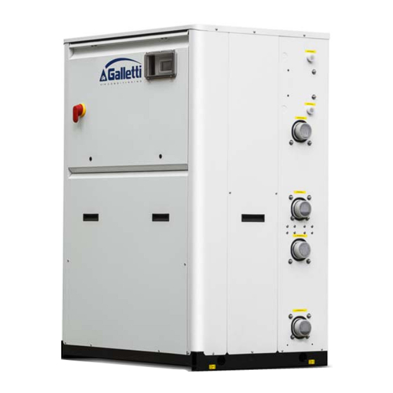
- Page 1 Technical manual Reversible Chillers and Heat Pumps - LEW SERIES 40 - 420 kW...
- Page 2 Page 2 of 56 RG66006951‐Rev.01 ...
-
Page 3: Table Of Contents
Contents CONTENTS ..............................3 1 GENERAL DESCRIPTION ........................5 1.1 LEW UNITS .............................. 5 1.1.1 P RODUCT CONFIGURATIONS ........................5 1.1.2 C ONFIGURATION AND ACCESSORIES ....................6 1.1.3 F IELD OF APPLICATION ........................... 7 1.1.4 P RODUCT INNOVATION ......................... 10 1.2 ... - Page 4 Declaration of conformity The declaration of conformity is attached to each machine Page 4 of 56 RG66006951‐Rev.01 ...
-
Page 5: 1 General Description
General description LEW units LEW reversible water chillers and heat pumps are air or process fluid conditioning units, designed for both domestic and industrial use and in operation 24 hours a day. They cover a thermal output range from 40 to 429 kW, guaranteeing a high level thermodynamic performance and a wide range of configuration possibilities, both in accessories and cooling circuit. LEW machines have been built in a fully faired framework to make the assembly extremely silent. They can therefore be installed in open environments without needing to be closed off. The all‐new new rounded‐off shape enhances their appearance. The exclusive use of R410A refrigerant and of high‐quality components in the chiller, hydraulic and electrical parts makes the LEW units state‐of‐the‐art chillers in terms of efficiency, reliability and emitted sound output. ... -
Page 6: Configuration And Accessories
1 ‐ Identification symbol of Hiref Model (e.g.: “LEW” unit) 2 ‐ Unit sizes expressed in rated chilling output x10 [kW] (e.g.: 70 kW) 3 ‐ Efficiency Pack: cooling circuit and compressor layout (e.g.: Efficiency Pack 2) 4 ‐ Machine version (e.g.: “C”, Chiller) 5 ‐ Machine execution (e.g.: “S” soundproofing not available) 1.1.2 Configuration and accessories List of standard features R410A refrigerant Scroll compressors Galvanised and painted sheet-metal structure Flow switch included Brazed plate heat exchangers Second set point on utility side that can be activated from an external input ... -
Page 7: Field Of Application
wooden cage wooden cage 9 - Remote control CMP9 absent Simplified remote control panel Remote display for standard microprocessor Not available if Field 2 = B,C Remote display for programmable microprocessor Not available if Field 2 = 0,A 10 - External insulated hydraulic module separated from the main unit CMP10 No hydraulic module LP utility pump + LP dissipation... - Page 8 DISSIPATION UTILITY LEW C machines are designed for cold‐only production: in the utility circuit only the production of chilled water is envisaged. The LEW H machines are reversible heat pumps: in the utility circuit hot water and chilled water can be produced alternatively. ...
- Page 9 Air‐conditioning applications often need to be able to dispose of heat to heat up domestic hot water or for post‐heating control in air treatment facilities where an autonomous Temperature and humidity control will be implemented. The heat required can be drawn from the condensing section of the thermodynamic unit, which is at a higher temperature. If only part of the heat is drawn, a de‐superheater sends gas‐sensitive heat to the delivery pipe towards the third thermal source at a higher temperature. Upon specific demand, all cold‐only units of the LEW series can be equipped with a de‐superheater for partial heat recovery. ...
-
Page 10: Product Innovation
1.1.4 Product innovation LEW units provide excellent thermodynamic performance and maximum flexibility of use thanks to constant product research. The joint application of scroll compressors, advanced control systems and R410A refrigerant gas achieves compact circuits and high COPs. The possibility of keeping the evaporator on the inside allows you not to add glycol to the water in the system, with clear advantages in terms of thermodynamic performance, preservation from corrosion and respect for the environment. ... -
Page 11: Compressors
Table II – List and graphical representation of the layout of the components in four Efficiency Packs: Efficiency Pack ONE: Efficiency Pack ONE: Efficiency Pack TWO: Efficiency Pack TWO: Efficiency Pack THREE: Efficiency Pack THREE: Efficiency Pack FOUR: Efficiency Pack FOUR: Efficiency Pack FOUR: Solutions with more than one circuit provide the utmost reliability thanks to redundancy, while those with more than one compressor on a circuit provide partial loads with ideal efficiency, also thanks to increased heat exchange surfaces. 1.3.1 Compressors Only top international brand Scroll compressors are used on LEW units. Scroll compressors, up to a power output of 182 kW for single circuit, are the best solution in terms of reliability and efficiency. They also provide the lowest amount of sound emissions. Process optimisation, along with a carefully selected intrinsic volumetric compression ratio (RVI), clearly improves the isentropic compression performance and reduces energy losses. The use of a scroll compressor allows ... -
Page 12: De-Superheater For Partial Heat Recovery (Optional)
NOTE: due to thermal insulation the data plate (in compliance with PED CE 97/23) is not legible. However, the serial number of the heat exchanger and the declaration of conformity are both recorded during production and are an integral part of Hiref's archive. 1.3.3 De-superheater for partial heat recovery (optional) The option of partial heat recovery is implemented with a braze‐welded plate heat exchanger placed in series on the ... -
Page 13: Electronically Controlled Electric Expansion Valve
Refrigerant side cycle inversion valve Heat‐transfer fluid side cycle inversion valve 1.3.5 Electronically controlled electric expansion valve The electronically controlled valve with external equalisation and built‐in MOP function is managed by the software and therefore makes cooling circuit operation very efficient, stabilising and decreasing the power absorbed by the system when a sudden thermal load variation occurs. The shutter in the central part of the valve can always slide vertically with an ample stroke allowing variation of the degree of opening of the orifice of the fluid passage. Using this valve reduces compressor energy consumption when the surrounding conditions bring the pressure difference between the evaporator and the air conditioner below 5 bar, thus improving performance. ... -
Page 14: Other Cooling Components
1.3.6 Other cooling components ‐ Molecular sieve filter dryer ‐ Sight glass with humidity indicator ‐ One‐way valves (only reversible heat pump) ‐ Liquid receiver marked in compliance with EC Directive 97/23 PED (only reversible heat pumps or units with remote condenser) ‐ High and low pressure switches Schrader valves for control and/or maintenance Page 14 of 56 RG66006951‐Rev.01 ... - Page 15 Diagram of the dual‐circuit cold‐only version (please note: this is a standard layout, refer to the layout enclosed with the unit). To consult the layouts, please refer to the symbols in the following table. Page 15 of 56 RG66006951‐Rev.01 ...
- Page 16 Diagram of the dual‐circuit reversible heat pump version (please note: this is a standard layout, refer to the layout enclosed with the unit). Page 16 of 56 RG66006951‐Rev.01 ...
- Page 17 Reference table for numbering used in layouts Page 17 of 56 RG66006951‐Rev.01 ...
-
Page 18: Electric Panel
Electric panel The electric panel is built and wired in accordance with standard EN 60204‐1. The electric panel is accessed from the front of the machine. Before it can be accessed, the unit must be disconnected from the power supply using the main switch, which functions as a door‐lock. All the remote controls are implemented with low voltage signals at 24 V, powered by an isolation transformer positioned inside the control board. All the control boards have an air circulation system with auxiliary fans. The position of the main switch makes wiring operations in the work site easier. This avoids several difficult operations as well as having to twist the power cords. All the utilities are protected against surges and short circuits. The circuit breaker set‐up can be configured for any load (optional). Thermal protection, however, is carried out by thermistor chains. These are set in the windings of each electric motor and are controlled by onboard ... -
Page 19: 2 Main Units Technical Data
Main units technical data The following chapter provides the technical data for the LEW unit. Performance values are accurately reported and can be interpolated to know specific operating conditions. Table I – Technical data of LEW chillers in standard operating conditions RATED TECHNICAL DATA OF LEW WATER CHILLERS@ 12/7°C; 15/30°C Efficiency pack 1 2 1 2 1 2 1 2 1 2 LEW CS / CL 41 42 51 52 61 62 71 72 81 82 Cooling capacity kW 51.9 51.1 60.2 60.1 69.1 69.2 ... - Page 20 RATED TECHNICAL DATA OF LEW WATER CHILLERS@ 12/7°C; 15/30°C 1 2 4 1 2 3 4 4 Efficiency pack 161 162 164 181 182 184 204 214 LEW CS / CL 174.9 175.1 176.2 204.5 204.8 198.9 219.1 235.1 Cooling capacity kW 32.1 32.1 31.9 37.9 37.9 36.4 39.3 42.7 Rated absorbed power ...
- Page 21 RATED TECHNICAL DATA OF LEW WATER CHILLERS@ 12/7°C; 40/45°C 30% glyc. Efficiency pack 1 2 1 2 1 2 1 2 1 2 LEW DS / DL 41 42 51 52 61 62 71 72 81 82 43.06 43.06 50.6 50.6 57.9 57.8 65.7 65.8 75.5 75.5 Cooling capacity kW 12.8 12.8 ...
- Page 22 RATED TECHNICAL DATA OF LEW WATER CHILLERS@ 12/7°C; 40/45°C 30% glyc. 1 2 4 1 2 3 4 4 Efficiency pack 161 162 164 181 182 184 204 214 LEW DS / DL 149.4 149.5 150 175 174.9 169.6 187 201.2 Cooling capacity kW 42.6 42.6 75.1 50 50 48.6 52.7 57.3 Rated absorbed power kW ...
- Page 23 Table II – Technical data of LEW heat pumps in standard operating conditions RATED TECHNICAL DATA OF LEW HEAT PUMPS @ 15/10°C; 40/45°C Efficiency pack 1 2 1 2 1 2 1 2 1 2 LEW HS / HL – LEW WS / WL 41 42 51 52 61 62 71 72 81 82 Cooling capacity kW 42.7 50.85 50.86 58.19 58.13 66.09 66.14 75.74 75.81 43.31 Utility side pressure drops ...
- Page 24 RATED TECHNICAL DATA OF LEW HEAT PUMPS @ 15/10°C; 40/45°C 1 2 4 1 2 3 4 4 Efficiency pack 161 162 164 181 182 184 204 214 LEW HS / HL – LEW WS / WL Cooling capacity kW 149.21 149.37 149.82 177.59 177.67 172.56 187.01 204.32 Utility side pressure drops kPa 38 38 38 33 33 32 37 ...
-
Page 25: Performance Of Lew C, D, H, Wheat Pump Units
Performance of LEW C, D, H, W heat pump units All the data in the paragraph refers to ΔT = 5°C on the evaporation and condensation side. Pf = chiller power [kW] ; Pa = absorbed power [kW]. In order to calculate the thermodynamic EER and COP factors, take the Pf / Pa ratio. The performance was calculated with different glycol percentages in a solution, even though from a thermodynamic point of view, with up to 30% of glycol in a solution, there is a minor performance drop: nonetheless refer to paragraph 4.1 “Use of glycol solutions” for further information. Table III: performance of LEW C D H units with cold water production mode. LEW C LEW D LEW H Tcond 10/30 15/30 20/30 30/35 35/40 40/45 10/30 15/30 20/30 [°C] Tev Size Pf Pa Pf ... - Page 26 20/15 358.8 48.7 402.9 57.6 353.6 50.4 344.8 327.5 59.6 309.1 65.9 370.3 46.9 368.1 47.4 365.3 48.1 LEW 15/10 308.2 47.8 307 48.4 304 49.3 296.7 53.1 281.1 59.3 265.5 65.4 318.0 45.6 317 46.3 311.7 47.5 244 10/5 263.8 ...
- Page 27 5/0 128.7 26.4 123.45 33.75 118.2 41.1 0/‐5 110.8 26.2 107.3 33.5 103.8 40.8 15/10 194.9 184.3 37.9 172.4 46.5 10/5 170.5 30.8 161.65 38.65 152.8 46.5 LEW 141/2 5/0 148.1 30.5 141.55 38.45 46.4 0/‐5 127.6 30.2 123.05 38.1 118.5 46 ...
-
Page 28: Noise Emission
Noise emission Table V: sound emissions for LEW ‐ Lw models: Sound power ‐ Lp: Sound pressure Sizes: 040 050 060 070 080 090 110 130 140 160 180 200 210 240 280 310 340 370 420 484 Standard 72 72 73 73 74 76 76 77 80 80 81 81 81 82 ... - Page 29 Table VII: overall dimensions of the frames of the main units (F_) Frame of the main Height (H) Width (L) Depth (D) unit 1594 F1 1174 772 F2 1594 1644 1854 F3 2374 877 Page 29 of 56 RG66006951‐Rev.01 ...
-
Page 30: Overall Drawings Of The Main Units
Overall drawings of the main units HF64000737 overall drawing Page 30 of 56 RG66006951‐Rev.01 ... - Page 31 HF64000614 overall drawing Page 31 of 56 RG66006951‐Rev.01 ...
- Page 32 HF64000592 overall drawing Page 32 of 56 RG66006951‐Rev.01 ...
- Page 33 HF64000608 overall drawing Page 33 of 56 RG66006951‐Rev.01 ...
- Page 34 HF64000581 overall drawing Page 34 of 56 RG66006951‐Rev.01 ...
- Page 35 HF64000609 overall drawing Page 35 of 56 RG66006951‐Rev.01 ...
- Page 36 HF64001344 overall drawing Page 36 of 56 RG66006951‐Rev.01 ...
- Page 37 HF64000803 overall drawing Page 37 of 56 RG66006951‐Rev.01 ...
- Page 38 HF64000627 overall drawing Page 38 of 56 RG66006951‐Rev.01 ...
-
Page 39: 3 Technical Data Of Optional Hydronic Modules
Technical data of optional hydronic modules Hydronic modules, recommended as an optional feature for LEW units, bring together, in just a single, compact and silent solution, the main components of the primary circuit of the hydraulic system served by LEW machines. Each hydraulic module contains both circuits: ‐ ON/OFF hydraulic pump ‐ Blade‐type flow switch to prevent ice from forming, which is caused by the evaporation of the refrigerant in the plate heat exchanger. (LEW C D units have a flow switch on the utility side, LEW W H units have a flow switch both on the utility and the source side) ‐ Expansion vessel to manage changes in volume affecting the amount of water contained in the LEW unit and the module itself ‐ Safety valve (set to 3 bar as standard) The module has its own electric panel, which powers the pumps, protects them with motor overload protections and receives the consent from the LEW units. The power is not supplied by the LEW unit, but directly by the external line. The module is insulated to reduce the sound emissions of the pumps. Characteristic curves of the hydraulic pumps associated to the units The graphics displayed in this paragraph show the useful head (net with the internal losses of the units) of the HP pumps and LP pumps in the optional hydronic module. At the nominal flow rates listed in this chapter in Tables I and II, the low‐pressure LP pumps provide 60 kPa of useful head on the utility side and 70 kPa on the dissipation side. The high‐pressure HP pumps provide a useful head equal to 140 kPa for both hydraulic circuits. ... - Page 40 Useful head for LEW 091, 092 pumps on utility side Useful head for LEW 111, 112, 131, 132 pumps on utility side Useful head for LEW 141, 142, 144 pumps on utility side Useful head for LEW 161, 162, 164 pumps on utility side Useful head for LEW 181; 182; 184 pumps on utility side Useful head for LEW 204 pumps on utility side Useful head for LEW 214 pumps on utility side Useful head for LEW 243, 244 pumps on utility side Page 40 of 56 RG66006951‐Rev.01 ...
- Page 41 Useful head for LEW 283, 284 pumps on utility side Useful head for LEW 314 pumps on utility side Useful head for LEW 344 pumps on utility side Useful head for LEW 374 pumps on utility side Useful head for LEW 424 pumps on utility side Useful head for LEW 484 pumps on utility side Useful head for LEW 041, 042 pumps on dissipation side Useful head for LEW 051, 052 pumps on dissipation side Page 41 of 56 RG66006951‐Rev.01 ...
- Page 42 Useful head for LEW 061, 062 pumps on dissipation side Useful head for LEW 071, 072 pumps on dissipation side Useful head for LEW 081, 082 pumps on dissipation side Useful head for LEW 091, 092 pumps on dissipation side Useful head for LEW 111, 112 pumps on dissipation side Useful head for LEW 131, 132 pumps on dissipation side Useful head for LEW 141, 142 pumps on dissipation side Useful head for LEW 144 pumps on dissipation side Page 42 of 56 RG66006951‐Rev.01 ...
- Page 43 Useful head for LEW 161, 162, 164 pumps on dissipation side Useful head for LEW 181, 182, 184 pumps on dissipation side Useful head for LEW 204 pumps on dissipation side Useful head for LEW 214 pumps on dissipation side Useful head for LEW 243 pumps on dissipation side Useful head for LEW 244, 283, 284 pumps on dissipation side Useful head for LEW 314 pumps on dissipation side Useful head for LEW 344 pumps on dissipation side Page 43 of 56 RG66006951‐Rev.01 ...
- Page 44 Useful head for LEW 374 pumps on dissipation side Useful head for LEW 424 pumps on dissipation side Useful head for LEW 484 pumps on dissipation side Page 44 of 56 RG66006951‐Rev.01 ...
-
Page 45: Overall Dimensions And Weight Of Optional Hydronic Modules
Overall dimensions and weight of optional hydronic modules The tables below list the weights, reference drawings and overall dimensions of all optional hydronic modules. The overall drawings of the optional modules are reported in the following paragraph. They can be referred to by consulting the identification codes reported the tables in this paragraph. Table VIII: weight and reference drawings of optional modules with reference to the dimensions of the relative main unit and whether or not there is a water side cycle inversion valve. Optional hydronic module with pumps Optional Model Weight [kg] Overall Drawing module frame LEW 041 M1 391 HF64000799 LEW 042 HF64000799 LEW 051 HF64000799 LEW 052 HF64000799 LEW 061 HF64000799 LEW 062 HF64000799 LEW 071 HF64000799 LEW 072 ... -
Page 46: Overall Drawings Of Optional Hydronic Modules
Overall drawings of optional hydronic modules HF64000799 overall drawing Page 46 of 56 RG66006951‐Rev.01 ... - Page 47 HF64000906 overall drawing Page 47 of 56 RG66006951‐Rev.01 ...
- Page 48 HF64000908 overall drawing for LEW C units Page 48 of 56 RG66006951‐Rev.01 ...
- Page 49 HF64000908 overall drawing for LEW D W H units Page 49 of 56 RG66006951‐Rev.01 ...
-
Page 50: 4 Installation
Installation Installation clearance requirements The hydraulic connections are all foreseen on the right side of the unit, when looking at the front panel. This way the back of the unit can be against the wall. It is essential to ensure the following service spaces: ‐ rear side: min. 0 m ‐ electric panel side: at least 1 m to guarantee access for inspections and/or for maintenance of cooling components ‐ right side: 1 m to be able to connect the hydraulic piping properly ‐ top side: min. 1 m ‐ left side: 0.5 m These distances refer to standard versions of LEW units; the same considerations apply to the optional hydronic modules. When installing the unit, for safety purposes, make sure that the room temperature does not exceed 50°C (with unit on or off). ... - Page 51 Inertial Tank Ts °C Outlet water Inlet water T T A standard feature of LEW units is a device to control the water flow rate (blade-type flow switch supplied). Any tampering with this device will immediately invalidate the warranty. We recommend installing a metal net filter on the water inlet piping.
-
Page 52: 5 Operating Limits
Operating limits This paragraph reports a list of operating limits for the LEW chillers relating to the water outlet temperature on the utility side and water inlet temperature at the dissipation exchanger. Applications with water T exceeding the limits indicated they must run with R134a refrigerant (available upon request). You can contact your local Agent for related details. Operating range of LEW units in cooling mode and heat pump mode: Water can be produced at temperatures below 5°C (up to ‐10°C) using glycol solutions. This lowers the freezing point as shown in the following table: Minimum temperature of 5 °C 2°C ‐1 °C ‐5°C ‐10 °C produced water Percentage in weight of 0 % 10 % 25 % 30 % ethylene glycol Freezing temperature of 0 °C ‐4 °C ‐ 8 °C ‐14 °C ‐18 °C mixture If the water produced is below 0°C, a special insulation needs to be applied to the cold pipes to prevent ice from forming. This is why applications with temperatures produced below 0°C must be considered as special applications. ... -
Page 53: Working Limits
The machines' performance can be calculated with the selection software. Working limits ‐ Heat transfer fluid: water or mixture of water and max 30% glycol antifreeze ‐ Maximum water side pressure: = 3 bar ‐ Maximum pressure on high pressure side = 45 bar‐r (**) ‐ Maximum ambient T = 45 °C ‐ Minimum ambient T= ‐10 °C ‐ Maximum pressure on low pressure side = 29 bar‐r (*) ‐ Power supply voltage: = +/‐ 10% compared to plate voltage ‐ Maximum storage T = + 50 °C ‐ Minimum storage Temp ... -
Page 54: 6 Calibration Of Control Devices
Calibration of control devices All the control devices are set and tested in the factory before the unit is dispatched. However, after the unit has been in service for a reasonable period of time you can perform a check on the operating and safety devices. The calibration values are reported in Tables I and II. All the servicing operations performed on the control equipment are considered as extraordinary maintenance and must be carried out EXCLUSIVELY BY QUALIFIED PERSONNEL: incorrect calibration values can cause serious damage to the unit and serious injury to people. - Page 55 Attention: do not modify the calibration of the maximum pressure switch. Should the latter fail to work, rising pressure causes the high pressure safety valve to open. The high pressure switch must be reset manually; this is possible only when the pressure drops below the value indicated by the set differential (see Table II). Calibration of the minimum pressure switch The low pressure switch stops the compressor when the intake pressure falls below the set value for more than 120 seconds. It is reset automatically only when the pressure rises above the value indicated by the set differential (see Table II). Calibration of the service thermostat function This function starts and stops the compressors according to the water temperature reading at the chiller unit inlet [water returning from the system]. Refer to the section of the document on the microprocessor control for further details. Calibration of the antifreeze thermostat function The antifreeze probe is located at the evaporator outlet and stops the compressor if the water temperature drops ...
- Page 56 40010 Bentivoglio (BO) Via Romagnoli 12/a Tel. 051/8908111 Fax. 051/8908122 Azienda certificata UNI EN ISO 9001 e OHSAS 18001 www.galletti.it...
Need help?
Do you have a question about the LEW CD and is the answer not in the manual?
Questions and answers