Table of Contents
Advertisement
Advertisement
Table of Contents

Related Manuals for Cannon CT-2000


Summary of Contents for Cannon CT-2000
- Page 1 CT-2000 Constant Temperature Bath Instruction & Operation Manual 27.9991...
- Page 3 Copyright Copyright © 2019 CANNON Instrument Company®. All rights reserved. Trademarks CANNON® and the CANNON® logo are registered trademarks of Cannon Instrument Company®. Contact Address: CANNON Instrument Company® 2139 High Tech Road State College PA 16803, USA Phone: 1-814-353-8000; 1-800-676-6232...
-
Page 5: Table Of Contents
Overheat Thermistor ........................ 5 RTD Cutoff Detection ....................... 5 Liquid-Level Sensor ........................5 Specifications ........................7 Unpack & Assemble ......................8 Unpack the CT-2000 ........................8 Damaged Items ........................9 Assembly Procedure ........................9 Insert Viscometer Tubes/Thermometers ..................15 Thermometer Immersion ......................15 Filling the Bath .......................... - Page 6 Troubleshooting ......................36 Spare Parts List ....................... 38 Warranty ........................39 Products Limited Warranty ......................39 Reagent and Chemical Warranty....................39 Returning a Product to CANNON ....................40 Required Information ......................40 Hazardous Materials ....................... 40 Shipping Notification ......................40...
- Page 7 Figure 12: Remove Heater Housing ....................13 Figure 13: Install Motor-Stirrer ......................13 Figure 14: CT-2000 Electrical Connections ..................14 Figure 15: CT-2000 Top View shown without Hole Covers ............... 15 Figure 16: Filling the Bath ....................... 16 Figure 17: LCD Temperature Setting ....................18 Figure 18: Warm Start Display ......................
- Page 8 Table 3: Commands ........................33 Table 4: Troubleshooting Causes and Solutions ................36 Table 5: CT-2000 Spare Parts List ....................38 Table 6: Ideal Bath Liquid ....................... 43 Table 7: CT-2000 Bath Fluid Options (10 °C to 150 °C) ..............43...
-
Page 9: Contents
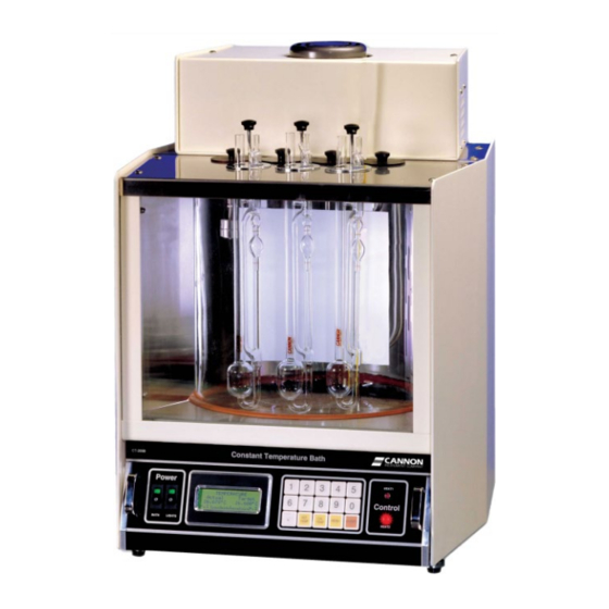
Figure 1: CANNON CT-2000 Extended Range Constant Temperature Bath Temperature Selection and Selection The CT-2000 offers convenient keypad entry of temperature settings up to three decimal places over the entire temperature range of the instrument. The bath temperature will remain stable within one 1/100ths of one degree of the temperature setting. -
Page 10: Bath Description
The CANNON CT-2000 is capable of maintaining temperatures of 10 °C to 100 °C within 0.01 °C and temperatures of 101 °C to 150 °C within 0.03 °C. (Temperature stability at or below ambient may vary depending on the quality of the external cooling unit.) -
Page 11: Astm D445 Specifications
ASTM D445 Specifications The CT-2000 temperature control provides the accuracy required by ASTM D445 for kinematic viscosity measurements. Cooling Coil A built-in cooling coil, when connected to tap water or a cooling system, permits operation to 10 ° C. CANNON Instrument Company | Introduction/Installation... -
Page 12: Notes/Cautions/Warnings
Manufacturer is not liable for any loss or damage directly or indirectly caused by use of the instrument or its consequences. This manual pertains directly to the CT-2000 constant temperature bath. For details relating to other accessories or equipment please refer to the appropriate manufacturer supplied documentation. -
Page 13: Safety Precautions
Keep all connections as neat as possible. • Unplug the power cord from the wall outlet if the CT-2000 will not be used for an extended period of time. Disconnect the power cord by pulling it out by the plug, never pull by the cord. - Page 14 (Material) Safety Data Sheets included with the bath fluid for more detail. Do not attempt to service the CT-2000 system by removing panels and Caution: trying to effect repairs. Contact CANNON regarding service and repair needs.
-
Page 15: Specifications
Specifications Table 1: CT-2000 Specifications Specifications Details Model CT-2000 Extended Range Constant Temperature Bath Methodology ASTM D445, ASTM D446, ISO 3104/3105 Applications Formulated oil analysis, hydraulic oil analysis, additive analysis, marine fuel testing, base stock analysis, light and heavy fuel testing, waxes/paraffin, crude oil testing, glycols Dimensions 43.8 cm ×... -
Page 16: Unpack & Assemble
Unpack & Assemble This section of the manual provides assistance in unpacking and assembling the CT-2000 Constant Temperature Bath. Unpack the CT-2000 The CANNON CT-2000 Constant Temperature Bath is shipped in several boxes containing the following components: • Bath housing, including the electronics drawer •... -
Page 17: Damaged Items
4. Inspect each component for signs of damage. Report any damages to the shipper and to Cannon Instrument Company immediately. Figure 4: Unpacked Primary Bath Components Damaged Items Retain all packing materials until the instrument is connected and functioning properly. If any component(s) must be returned to CANNON, the damaged item(s) should be packaged in the original shipping container. -
Page 18: Figure 7: Remove Top And Rear Top Covers
7. Place the rubber gasket around the top rim of the jar. The rubber may have to be trimmed slightly to allow the ends of the rubber gasket to meet, with no gap, when placed around the rim. Refer to Figure 9. CT-2000 Instruction Manual... -
Page 19: Figure 9: Placing Rubber Gasket Around Rim Of Jar
10. Remove the wrapping from around the two glass panels. Place the thinner of the two pieces of glass in the slot closest to the jar. Refer to Figure 11. Inner Wall Figure 11: Placing Inner Glass Plate CANNON Instrument Company | Unpack & Assemble... - Page 20 Replace the drawer in the slide tracks and push the drawer back into its opening. Insert the two power plugs into the rear of the drawer assembly. 15. Remove the motor-stirrer from its box. Remove the two screws on the top heater housing and lift off the housing. Refer to Figure 12. CT-2000 Instruction Manual...
-
Page 21: Figure 12: Remove Heater Housing
(offset slightly to the right or left). The motor-stirrer should now lie flat on the top of the bath. 17. Connect all plugs and probes to the correspondingly labeled sockets at the rear of the CT-2000 bath unit as shown in Figure 14 and in the following list. -
Page 22: Figure 14: Ct-2000 Electrical Connections
20. Plug the CT-2000 main power cord at the back of the electronics drawer into an outlet with electrical specifications matching the label on the rear of the instrument. -
Page 23: Insert Viscometer Tubes/Thermometers
Insert Viscometer Tubes/Thermometers The top cover of the CT-2000 contains seven apertures, 51 mm (2”) in diameter, for the insertion of viscometer tube holders. Two additional holes are provided for insertion of thermometers. Refer to Figure 15. Figure 15: CT-2000 Top View shown without Hole Covers... -
Page 24: Figure 16: Filling The Bath
The bath must be placed in its intended final position before adding Caution: bath fluid. Never move the CT-2000 when filled with bath fluid. Never use flammable bath liquids. Warning: 1. Make sure that the instrument power is OFF and select a bath liquid appropriate to your operating temperature range. -
Page 25: Drain The Bath
Warning: higher temperatures (100 °C to 150 °C). The bath liquid expands as the temperature increases. The CT-2000 bath jar is not designed to contain liquid under pressure. If the bath is overfilled the liquid may overflow and damage equipment. -
Page 26: Bath Operation
Cold Start The Cold Start is the normal start-up mode for the CT-2000. During the Cold Start process, the CT- 2000 performs several diagnostics (see Self-Test Sequence). At the conclusion of a successful test procedure, the results are briefly displayed on the LCD screen. The bath heaters are activated and the Bath Unit begins controlling the temperature according to the most recent temperature entry. -
Page 27: Warm Start
Warm Start condition and no further action is required. 4. If the bath continues to enter the Warm Start condition, consult CANNON for further assistance. Self-Test Sequence The CT-2000 start-up includes a self-test procedure encompassing key components of the system. -
Page 28: Figure 19: Normal Test Sequence Display
Voltage Levels Verifies power supply voltage levels (positive and negative). Figure 19 illustrates the LCD sequence for a normal self-test: Figure 19: Normal Test Sequence Display If the self-test sequence is accomplished successfully, the CT-2000 commences normal operations. CT-2000 Instruction Manual... -
Page 29: Figure 20: Self-Test Fail Warning Screen
LED will not light (see section Warm ENTER Start). In the event of a FAILED test, turn off the CT-2000 power for at least five seconds and then restart the unit. -
Page 30: Front Panel Operations
Check bath fluid levels before commencing with use of the CT-2000. Note: The front panel of the CT-2000 provides a Liquid Crystal Display (LCD) screen and a simple keypad interface as shown in Figure 23. Figure 23: CT-2000 Front Panel The keypad on the front panel of the CT-2000 consists of fifteen keys: •... -
Page 31: Enter
(unacceptable input), such as a temperature value outside the range of the unit. ENTER ENTER button is the most-used feature on the CT-2000 keypad. Each menu choice and numeric input must be confirmed by pressing the button. -
Page 32: Data Entry Errors
Input/output connections for the coil are located on the upper portion of the rear panel. Coolant temperature must be lower than the desired CT-2000 control temperature. Extreme temperatures or variability in the temperature of the coolant Caution: liquid may adversely affect the CT-2000 temperature control. -
Page 33: Calibrating The Ct-2000
Calibrating the CT-2000 The CT-2000 has the ability to be calibrated to a temperature reference standard for any desired temperature, Celsius or Fahrenheit. The controls for entering the target (desired) temperature and the calibration at this temperature are convenient and largely intuitive. The instrument stores calibration corrections for every temperature integer. -
Page 34: Calibration Theory
This calibration adjustment value for the bin is effective at all temperature ranges within 0.5 degrees of the temperature integer. The CT-2000 combines user calibration input with readings obtained by the temperature probe and data from the general bath offset, a protected menu option, which is preset at the factory by Cannon Instrument Company (see the MENU Options section for more information). -
Page 35: Menu Options
MENU Options The MENU selection from the CT-2000 keypad permits the user to access three functions: • Change to (C/F): Changes screen display to alternate temperature scale • Bath Temperature Offsets: Globally adjusts calibration data • COM Setup: Sets computer communication options... -
Page 36: General Bath Offset
General Bath Offset The General Bath Offset is a protected function of the CT-2000. This option is a global adjustment which is made at the factory by CANNON. In rare instances when this setting may need to be altered, the adjustment should be made in consultation with an authorized CANNON representative. -
Page 37: Communication Options
Change Port Speed The Change Port Speed option provides a speed setting for data transfer between the CT-2000 and a computer via the RS-232C connection. Select the baud rate (the default for most software is 9600) in bps (bits per second) from one of the following options: 1. -
Page 38: Keypad Sequence
MENU ENTER ENTER If the CT-2000 was previously configured to operate in a polled (RS-485) environment, the Communication Mode message appears on the LCD as shown in Figure 26. Figure 26: Communication Mode Display The last line on the LCD indicates that timed reports are disabled and the present mode is polled. -
Page 39: Keypad Sequence
Full Duplex (point-to-point) Connections The RS-232 interface is furnished for a direct connection between the CT-2000 and one computer. A DB-25 connector on the rear panel of the CT-2000 is configured as Data Communication Equipment (DCE). -
Page 40: Commands, Queries & Responses
Company, a disk or link will be sent to the user along with instructions on how to perform this upgrade. A download push button is located on the rear panel of the CT-2000. Pressing and holding this button for several seconds places the CT-2000 instrument in the download mode. -
Page 41: Table 3: Commands
If the command is not recognizable, ERROR is None displayed. For example, if this command is sent to a CT-2000 with an address of 5: /5CAD; then the response may be: -5CADYES Run a complete self-test like the one run at power up. A response... - Page 42 ERROR. For example, if this command requesting reports every one second interval is sent to a CT-2000 with an address of 3: /3CSR002; the response may be: -3CSRYES Set the desired target temperature of the bath as defined by the argument +&&&.&&&, in °C or °F as previously established.
- Page 43 This is followed by at least one space and then the desired temperature (to the thousandths of a degree). For example, if the following query is sent to a CT-2000 in °C with a target temperature of 40 °C and at address 3: /3QTR. This queries the temperature report.
-
Page 44: Troubleshooting
If items 4 or 5 fail (temperature probe functionality and/or heater operation), the bath may be non-operational. Consult Table 4 for assistance in troubleshooting your CT-2000. If the following table fails to resolve the difficulties, call your local CANNON representative for assistance. - Page 45 See Appendix I: Correcting Shaft & Air bubbles in the bath fluid Impeller Misalignment. • Bath fluid is too viscous for operation at this temperature. Replace with appropriate fluid. Refer to Appendix II: Choosing a Temperature Bath Liquid if needed. CANNON Instrument Company | Troubleshooting...
-
Page 46: Spare Parts List
Spare Parts List Table 5 provides a list of parts for the CT-2000 which may be ordered from CANNON upon request. Table 5: CT-2000 Spare Parts List Part Number Description 20.1 Pyrex Jar 12 x 12 20.22 Thermometer holder, rubber 20.26... -
Page 47: Warranty
(net of freight, handling charges and taxes), of any reagent or chemical sold by CANNON which does not conform to such weight, specifications and standards upon the prompt return of the unused portion. Except for replacement or refund of the net price, the... -
Page 48: Returning A Product To Cannon
Please contact CANNON before returning a product that could possibly contain hazardous material. Shipping Notification Products returned without CANNON’s prior authorization will not be accepted. The customer may be billed a testing fee if a product is returned to CANNON and found to be working properly. CT-2000 Instruction Manual... -
Page 49: Appendix I: Correcting Shaft & Impeller Misalignment
Appendix I: Correcting Shaft & Impeller Misalignment Motor-stirrer units supplied by Cannon Instrument Company are checked after assembly to ensure minimum run-out (deviation from concentric rotation) at the impeller end of the shaft. The following instructions are intended to assist those who may be experiencing excessive vibration in the motor-stirrer because of shaft run-out or misalignment of the impeller blades. - Page 50 This is a trial-and-error process which usually must be repeated several times. When the crayon makes a line at least two-thirds of the way around the shaft, the run-out is diminished to an acceptable level. A uniform line completely around the shaft would indicate no run-out detectable by this procedure. CT-2000 Instruction Manual...
-
Page 51: Appendix Ii: Choosing A Temperature Bath Liquid
Refer to Table 7 for a list of operating temperature ranges and suitable bath liquids for use in these ranges. Table 7: CT-2000 Bath Fluid Options (10 °C to 150 °C) Temperature Range (°C) Suitable Bath Liquids 10 °C to 20 °C... -
Page 52: Ibf Bath Oil
IBF Bath Oil IBF Bath Oil contains an oxidation inhibitor which reduces tendency to darken at higher temperatures. Viscosity is 36 cSt at 40 °C and 5.6 cSt at 100 °C. This oil is available from CANNON as part number 9726- L20. - Page 54 CANNON INSTRUMENT COMPANY® 2139 High Tech Road | State College, PA 16803 | USA 800-676-6232 | 814-353-8000 | Fax: 814-353-8007 sales@cannoninstrument.com | cannoninstrument.com...
Need help?
Do you have a question about the CT-2000 and is the answer not in the manual?
Questions and answers