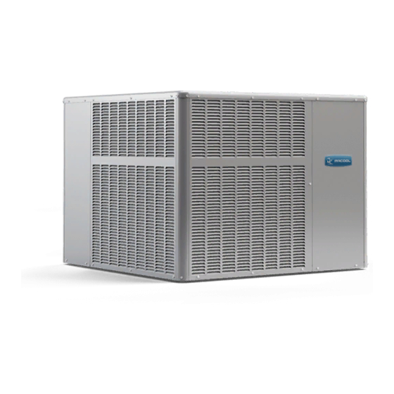
MrCool Signature Series Owners & Installation Manual
Hide thumbs
Also See for Signature Series:
- Owners & installation manual (59 pages) ,
- Manual (18 pages) ,
- Installation manual (15 pages)
Advertisement
Quick Links
The Signature Series is NOT designed for amateur installation. Installation SHOULD be performed by an authorized technician.
Please read this manual carefully before installation and keep it for future reference.
Owner & Installation
Manual
Signature Series
MPC*1M414A & MPH*1M414A
Residential Packaged Units
The Signature Series is NOT designed for amateur installation. Installation SHOULD be performed by an authorized technician.
Please read this manual carefully before installation and keep it for future reference.
Advertisement

Summary of Contents for MrCool Signature Series
- Page 1 The Signature Series is NOT designed for amateur installation. Installation SHOULD be performed by an authorized technician. Please read this manual carefully before installation and keep it for future reference. Owner & Installation Manual Signature Series MPC*1M414A & MPH*1M414A Residential Packaged Units The Signature Series is NOT designed for amateur installation.
-
Page 2: Table Of Contents
All other installation guidelines must also the unit. other appliance. Such actions could result in property Manufactured By MRCOOL LLC *F507296-C* CAUTION The installation of this appliance must conform to the requirements of the National Fire Protection Association; the jurisdiction should be consulted before installation is made. -
Page 3: Installation
The lengths of the forks of the forklift must be a minimum of 42”. also be observed. outdoor air stream. The outdoor fan is not designed to operate against any additional static pressure. Page 2 of 12 mrcool.com 507296-02C... -
Page 4: Electrical Wiring
Carefully remove outer packaging material and discard. Electrical Wiring corner and seal the shipping openings in the base from prevent air leakage during unit operation. the installer. Refer to the unit rating plate for maximum 507296-02C mrcool.com Page 3 of 12... -
Page 5: Duct System
CFM and static requirements of the job. They should not be sized to match the dimensions of the duct connections on the unit. changed Figure 3. 208/230 Line Voltage Wiring panel. Duct to unit connections must be sealed and Page 4 of 12 mrcool.com 507296-02C... -
Page 6: Filters
Heater Kit Accessory (if used) auxiliary heat. A heater kit accessory may also be used. To The condensate drain line must be properly trapped, routed to a suitable drain and primed prior to unit commissioning. access. 507296-02C mrcool.com Page 5 of 12... -
Page 7: Sequence Of Operation
The thermostat automatically Defrost Thermostat The defrost thermostat is located on the outdoor coil. thermostat contacts close and send a signal to the defrost control board to start the defrost timing. It also terminates Figure 6. Heater Kit Accessory Installation mrcool.com 507296-02C... - Page 8 It is intended that this board. In addition, the diagnostic LEDs will indicate a product should be set at the 60-minute time interval at initial installation. If the timing selector jumper is not in of an open pressure switch (see Table 3). 507296-02C mrcool.com...
- Page 9 3 Ton 3.5 Ton 4 Ton 5 Ton the suction superheat value to judge performance. When checking performance of a unit that uses an expansion Table 6. Heat Pump Heating System Performance system performance. Values Page 8 of 12 mrcool.com 507296-02C...
-
Page 10: Maintenance
Table 7. Cooling Performance - AC Models 80 DB / 67 WB Deg. Air Temperature Entering Outdoor Coil, Degree F Return Air Cooling Input Pressure 65° 70° 75° 80° 82° 85° 90° 95° 100° 105° 110° 115° (1000 BTU) Suction 507296-02C mrcool.com... - Page 11 Suction Table 8. Heating Performance - HP Models 70 Deg. F Return Air Air Temperature Entering Outdoor Coil, Degree F Cooling Input Pressure 0° 5° 10° 17° 20° 25° 35° 40° 47° 50° 55° 60° (1000 BTU) Suction mrcool.com 507296-02C...
-
Page 12: Wiring Diagrams
Wiring Diagrams 208/230-1-60 POWER SUPPLY WITH MIN. 75 C COPPER WIRE J1-2 J1-1 BLACK J1-3 208V YEL W/ STRIPE 240V Figure 8. Connections Diagram - A/C Constant Torque 507296-02C mrcool.com Page 11 of 12... - Page 13 Figure 9. Connections Diagram - Heat Pump Constant Torque Page 12 of 12 mrcool.com 507296-02C...
- Page 14 Signature Series MPC*1M414A & MPH*1M414A Residential Package ELECTRICIAN and/or HVAC TECHNICIAN: LICENSE #: INSTALLATION DATE: INSTALLATION LOCATION: SERIAL NUMBER: The design and specifications of this product and/or manual are subject to change without prior notice. Consult with the sales agency or manufacturer for details.


Need help?
Do you have a question about the Signature Series and is the answer not in the manual?
Questions and answers