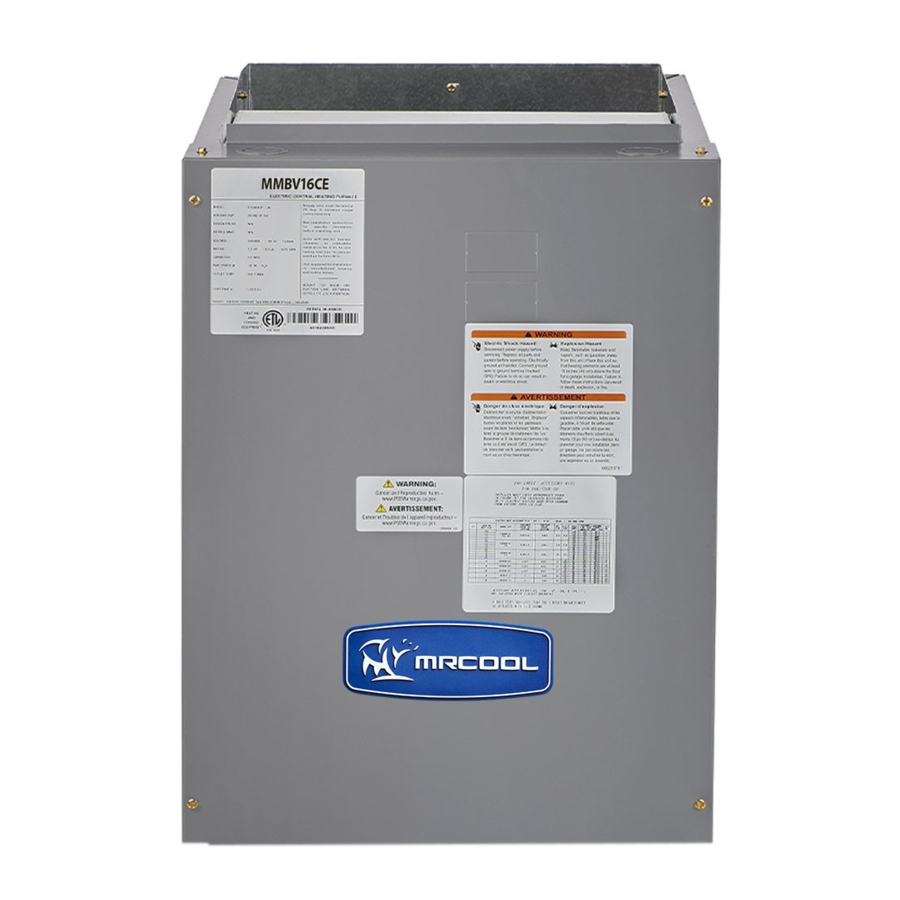
MrCool Signature Series Installation Manual
Modular blower
Hide thumbs
Also See for Signature Series:
- Owners & installation manual (59 pages) ,
- Manual (18 pages) ,
- Installation manual (21 pages)
Advertisement
Quick Links
Please read this manual carefully before installation and keep it for future reference.
Installation Manual
Signature Series
MMBV*E Modular Blower
Due to updates and constantly improving performance, the information and instructions within this
manual are subject to change without notice. Please visit www.mrcool.com/documentation to
ensure you have the latest version of this manual.
Version Date: 04-21-21
Advertisement

Summary of Contents for MrCool Signature Series
- Page 1 Signature Series MMBV*E Modular Blower Due to updates and constantly improving performance, the information and instructions within this manual are subject to change without notice. Please visit www.mrcool.com/documentation to ensure you have the latest version of this manual. Version Date: 04-21-21...
-
Page 2: Table Of Contents
Signature Series Modular Blower INSTALLATION INSTRUCTIONS This manual must be left with the homeowner for future reference. This is a safety alert symbol and should never be ignored. When you see this symbol on labels or in manuals, be alert to the potential for personal injury or death. -
Page 3: Installation
Horizontal installations can be left or right hand. Adequate support must be provided to insure cabinet integrity. Ensure that there is adequate room to remove service and access panels if installing in the horizontal position. horizontal coil installations. mrcool.com Page 2... - Page 4 20 in x 25 in 5 tons 960 sq. in. 576 sq. in. 576 sq. in. 1900 - 2100 CFM 20 in x 30 in (2) 24 in x 25 in Table 1. Recommended Remote Filter Sizes Page 3 mrcool.com...
-
Page 5: Condensate Drain Connection
Install a 2” trap in the primary drain line as close to the unit as practical. Make sure that the top of the trap is below connection to the drain pan to allow complete drainage of pan. mrcool.com Page 4... -
Page 6: Electrical Wiring
60 cycle, AC power supply. The units are internally factory wired for 240 volt installation. If 208 volt installation is desired, it will be necessary to change the black transformer lead in the blower cabinet control box to the 208V terminal on the transformer. Page 5 mrcool.com... -
Page 7: Setup
The data in the application table is categorized by unit size DEHUMIDIFY and mode of operation. Use the information provided to determine the CFM taps needed for cooling and heating. CUT TO ENABLE Figure 2. Motor Board Taps and Dehumidify Resistor mrcool.com Page 6... - Page 8 1400 1200* * This CFM is not approved for use with highest kW heater size. At the end of a call for cooling there is a blower delay of 1 minute. Table 2. Variable Speed Motor Application Page 7 mrcool.com...
-
Page 9: Sequence Of Operation
W is completed, and the heater sequencer is energized. A time delay follows before the heating elements and the indoor blower motor come on. Units with a second heat W on the thermostat sub-base or connected to a second stage on the sub-base. mrcool.com Page 8... -
Page 10: System Check
• Is the unit circuit breaker(s) rotated properly – ON up/ OFF down? • Are all access panels in place and secure? Refer to outdoor unit installation instructions for system start-up instructions and refrigerant charging instructions. Page 9 mrcool.com... -
Page 11: Replacement Parts
Installed By: Dealer: Address: Telephone # License # Contact Person: Other Equipment Installed: Equipment Type: Model # Serial # Installation Date: Equipment Type: Model # Serial # Installation Date: Equipment Type: Model # Serial # Installation Date: mrcool.com Page 10... - Page 12 Counterflow Upflow Left to Right Airflow Right to Left Airflow Horizontal Figure 3. Page 11 mrcool.com...
- Page 13 Figure 4. Wiring Diagram for Variable Speed Blower mrcool.com Page 12...
- Page 14 Y/Y2 2-Stage System only; for single-stage systems, jumper Y1 to Y2 Heat Only Electric Thermostat Furnace 2nd Stage Electric Heat if wired Connect common wired to thermostat only if required. See thermostat instructions. Figure 5. Field Connections Page 13 mrcool.com...
- Page 15 Please read this manual carefully before installation and keep it for future reference. Signature Series Consult with the sales agency or manufacturer for details.


Need help?
Do you have a question about the Signature Series and is the answer not in the manual?
Questions and answers