MrCool Signature Series Owners & Installation Manual
Hide thumbs
Also See for Signature Series:
- Owners & installation manual (59 pages) ,
- Manual (18 pages) ,
- Installation manual (15 pages)
Table of Contents
Advertisement
The Signature Series is NOT designed for amateur installation. Installation SHOULD be performed by an authorized technician.
Please read this manual carefully before installation and keep it for future reference.
Owner & Installation
Manual
Signature Series
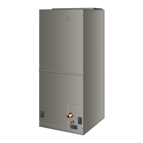
MAHM*ETA AIR Handler
The Signature Series is NOT designed for amateur installation. Installation SHOULD be performed by an authorized technician.
Please read this manual carefully before installation and keep it for future reference.
Advertisement
Table of Contents

Related Manuals for MrCool Signature Series


Summary of Contents for MrCool Signature Series
- Page 1 The Signature Series is NOT designed for amateur installation. Installation SHOULD be performed by an authorized technician. Please read this manual carefully before installation and keep it for future reference. Owner & Installation Manual Signature Series MAHM*ETA AIR Handler The Signature Series is NOT designed for amateur installation. Installation SHOULD be performed by an authorized technician.
-
Page 2: Table Of Contents
HVAC installer or and protective clothing. equivalent, service agency, or the gas supplier. Manufactured By MRCOOL LLC Hickory, KY 42051 IMPORTANT The Clean Air Act of 1990 bans the intentional venting of refrigerant (CFCs, HCFCs and HFCs) as of July *P507788-01C* 1, 1992. - Page 3 PIPING PLATE (3) LINE (2-1/4 x 3-3/4) LIQUID FILTER LINE ACCESS 1-1/8 1-1/8 20-3/8 1-1/8 (13) (29) (29) (29) (518) OPENING OPENING FRONT VIEW SIDE VIEW NOTE: 036 / 042 Dimensions 1156 1194 1362 1397 1518 Page 2 of 20 mrcool.com 507788-01C...
-
Page 4: Shipping And Packing List
18 inches These instructions are intended as a general guide and do authorities having jurisdiction before installation. instructions can result in death, explosion, 507788-01C mrcool.com Page 3 of 20... -
Page 5: Installation Clearances
NOTE: NOTE: HORIZONTAL DRAIN PAN (MUST BE REMOVED) UP-FLOW / DOWN-FLOW Installation Clearances DRAIN PAN Non-Ducted Return Closet Installation Figure 1. bottom to form a return air plenum. It may also be installed Page 4 of 20 mrcool.com 507788-01C... - Page 6 Figure 2. Right-Hand Discharge Remove plastic plug from left hole on coil front end seal and reinstall plug in back hole. connections. With access door removed, remove drain line plugs to install drain lines. 507788-01C mrcool.com Page 5 of 20...
-
Page 7: Condensate Drain
Figure 5. pipe to the outside of the building, is required in all NOTE: pan. In some localities, local codes may require a secondary drain pan for any horizontal installation. support rail as illustrated. Page 6 of 20 mrcool.com 507788-01C... - Page 8 FIELD-PROVIDED FITTINGS AND DRAIN CORNER DRAIN LINES. GREEN MAIN RED SECONDARY DRAIN PAN DRAIN PLUG DRAIN PLUG Figure 8. Drain Line Connections Figure 7. Sloping the Unit for Proper Drainage Install Condensate Drain connections. 507788-01C mrcool.com Page 7 of 20...
-
Page 9: Duct System And Filters
Correct any leaks found. Field-Fabricated Return Air Duct Flange For Horizontal Applications A return air duct system is recommended, but not factory- closet, run a full-size return connection to a location outside the closet. Page 8 of 20 mrcool.com 507788-01C... -
Page 10: Brazing Refrigerant Lines
Make sure that the suction line is insulated over the entire exposed length and that neither suction nor 507788-01C mrcool.com Page 9 of 20... - Page 11 COOL BEFORE REMOVING WET RAG FROM CTXV SENSING BULB AND PIPING PANEL AREA. REPEAT PREVIOUS PROCEDURE FOR LIQUID REFER TO INSTRUCTIONS PROVIDED WITH OUTDOOR LINE. UNIT FOR LEAK TESTING, EVACUATING AND CHARGING PROCEDURES Figure 10. Brazing Connections Page 10 of 20 mrcool.com 507788-01C...
-
Page 12: Sealing The Unit
Wiring must conform to the current National Electric IMPORTANT Part I, CSA Standard C22.1, and local building codes. for minimum circuit ampacity and maximum over- any gaps or holes in the cabinet. current protection size. 507788-01C mrcool.com Page 11 of 20... - Page 13 208 volt terminal on the transformer. connection box. 208 / 240 VOLT TRANSFORMER PRIMARY SECONDARY Replace the air handler access panel. 240 Volts 208 Volts Figure 13. Converting Unit from 240VAC to 208VAC SIDE Figure 11. Electrical Connections Page 12 of 20 mrcool.com 507788-01C...
- Page 14 Figure 14. Typical Wiring Diagram MAHM*ETA 507788-01C mrcool.com Page 13 of 20...
- Page 15 NOTE Figure 15. Page 14 of 20 mrcool.com 507788-01C...
- Page 16 1625 1595 1565 1520 1490 1815 1780 1760 1730 1685 1900 1870 1835 1810 1765 High static application 1980 1955 1920 1890 1860 Table 2. MAHM*ETA Constant Torque Air Handler Wet Air Flow Data 507788-01C mrcool.com Page 15 of 20...
-
Page 17: Operation Inspection
Set the thermostat 5ºF higher than the indoor of Tap 4) * Tap 4 is minimum setting for electric heat should cycle off. Air handler should cycle off 45 seconds after the outdoor unit shuts off. Table 3. Page 16 of 20 mrcool.com 507788-01C... -
Page 18: Operation
Circuit R-W1 energizes a heat sequencer. (less than 50psi). If the coil cannot be cleaned using W1 on the thermostat. They may also be connected to a second thoroughly after cleaning. heating stage W2 on the thermostat sub-base. (salt). 507788-01C mrcool.com Page 17 of 20... -
Page 19: Cabinet Insulation
1. CUT INSULATION IN X PATTERN 2. APPLY GLUE 3. PRESS GLUED TABS AGAINST CABINET Figure 16. Recommended Blower Speed Taps Page 18 of 20 mrcool.com 507788-01C... - Page 20 Temperature Rise = __________ Electrial Connections Tight THERMOSTAT DRAIN LINE Adjusted and Programmed Leak Free Operation Explained to Owner Explained Operation of System to Homeowner Technician’s Name:_______________________Date Start−Up & Performance Check Completed__________ Figure 17. 507788-01C mrcool.com Page 19 of 20...
- Page 21 Temperature Rise = __________ Electrial Connections Tight THERMOSTAT DRAIN LINE Adjusted and Programmed Leak Free Operation Explained to Owner Explained Operation of System to Homeowner Technician’s Name:_______________________Date Start−Up & Performance Check Completed__________ Figure 18. Page 20 of 20 mrcool.com 507788-01C...
- Page 22 Signature Series MAHM*ETA Air Handler ELECTRICIAN and/or HVAC TECHNICIAN: LICENSE #: INSTALLATION DATE: INSTALLATION LOCATION: SERIAL NUMBER: The design and specifications of this product and/or manual are subject to change without prior notice. Consult with the sales agency or manufacturer for details.
Need help?
Do you have a question about the Signature Series and is the answer not in the manual?
Questions and answers