
Related Manuals for Baumer Hübner POG 90


Summary of Contents for Baumer Hübner POG 90
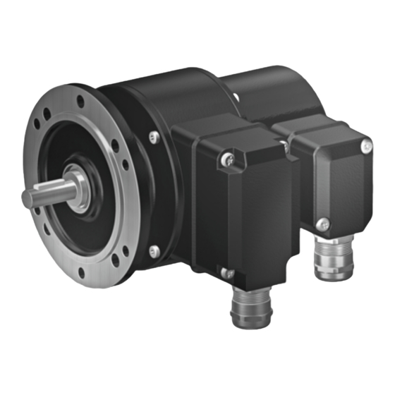
- Page 1 Montage- und Betriebsanleitung Installation and operating instructions POG 90 + ESL Kombination Drehimpulsgeber + Elektronischer Drehzahlschalter Combination Incremental Encoder + Electronic Speed Switch...
-
Page 2: Table Of Contents
Baumer Hübner Federscheiben-Kupplung K 35 ............... Schritt 5 - Klemmenkasten POG 90 ..................... Schritt 6 - Klemmenkasten POG 90 ..................... Schritt 7 und 8 - Klemmenkasten POG 90 ..................4.10 Schritt 9 - Klemmenkasten POG 90 ..................... 4.11 Schritt 10 - Klemmenkasten POG 90 .................... - Page 3 Baumer Hübner K 35 spring disk coupling is used ............. Step 5 - Terminal box POG 90 ......................... Step 6 - Terminal box POG 90 ......................... Step 7 and 8 - Terminal box POG 90 ....................4.10 Step 9 - Terminal box POG 90 ......................... 4.11 Step 10 - Terminal box POG 90 ......................
-
Page 4: Allgemeine Hinweise
Hinweis zur Gewährleistung eines einwandfreien Betriebes des Produkts Information Empfehlung für die Produkthandhabung Die Kombination aus dem Drehimpulsgeber POG 90 und dem elektronischen Drehzahlschalter ESL ist ein opto-elektronisches Prä zi sionsmessgerät, das mit Sorgfalt nur von technisch qualifi- ziertem Per sonal gehandhabt werden darf. -
Page 5: General Notes
Informations to ensure correct product operation Information Recommendation for product handling The combination of the incremental encoder POG 90 and the electronic speed switch ESL is an opto electro nic precision measurement device which must be handled with care by skilled personnel only. -
Page 6: Sicherheitshinweise
Sicherheitshinweise Sicherheitshinweise Verletzungsgefahr durch rotierende Wellen Haare und Kleidungsstücke können von rotierenden Wellen erfasst werden. • Vor allen Arbeiten alle Betriebsspannungen ausschalten und Maschinen stillsetzen. Zerstörungsgefahr durch elektrostatische Aufladung Die elektronischen Bauteile in der Kombination sind empfindlich gegen hohe Spannungen. •... -
Page 7: Security Indications
Security indications Security indications Risk of injury due to rotating shafts Hair and clothes may become tangled in rotating shafts. • Before all work switch off all operating voltages and ensure machinery is stationary. Risk of destruction due to electrostatic charge Electronic parts contained in the combination are sensitive to high voltages. -
Page 8: Vorbereitung
EURO flange B10 Klemmenkastendeckel POG 90 Terminal box cover POG 90 Platine mit Anschlussklemmen POG 90, Board with connecting terminal POG 90, siehe Abschnitt 4.9 und 6.1 see section 4.9 and 6.1 Kombi-Torx-Schraube M3x10 mm Screw with torx and slotted drive M3x10 mm SUB-D Stecker am Gebergehäuse... -
Page 9: Zur Montage Erforderlich Bzw. Empfohlen (Nicht Im Lieferumfang Enthalten)
Vorbereitung - Montage / Preparation - Mounting zur Montage erforderlich bzw. empfohlen required resp. recommended for mounting (nicht im Lieferumfang enthalten) (not included in scope of delivery) Anbauvorrichtung, kundenspezifi sch Installation fi tting, customized Befestigungsschrauben für Anbauvorrichtung Fixing screws for installation fi tting ISO 4017, ISO 4017, M6x16 mm M6x16 mm Federscheibenkupplung K 35,... -
Page 10: Montage
Montage / Mounting Montage Mounting Schritt 1 Step 1 zul. Anzugsmoment Max tightening torque = 2-3 Nm Größe: 2,5 mm Size: 2.5 mm Schritt 2 Step 2 SW 10 mm 10 mm a/f * siehe Seite 6 see page 6 Motorwelle einfetten! Lubricate motor shaft! Die Antriebswelle sollte einen mög-... -
Page 11: Schritt 3
Montage / Mounting Schritt 3 Step 3 SW 10 mm 10 mm a/f Schritt 4 Step 4 Größe: 2,5 mm Size: 2.5 mm zul. Anzugsmoment Max tightening torque = 2-3 Nm * siehe Seite 6 see page 6 MB154.2 pog90-esl_mb (09A1) ... -
Page 12: Max. Zulässige Anbaufehler Unter Verwendung Der Baumer Hübner Federscheiben-Kupplung K 35
Montage / Mounting Max. zulässige Anbaufehler Max. permissible mounting tolerance unter Verwendung der Baumer Hübner when the Baumer Hübner Federscheiben-Kupplung K 35 K 35 spring disk coupling is used Kombinationen mit Vollwelle sollten Combinations with a solid shaft should be unter Verwendung der Baumer Hübner driven through the Baumer Hübner K 35 Federscheiben-Kupplung K 35 (Zubehör) -
Page 13: Schritt 5 - Klemmenkasten Pog 90
Montage / Mounting Schritt 5 - Klemmenkasten POG 90 Step 5 - Terminal box POG 90 11 * Größe/Size Torx TX20 SW 22 mm 22 mm a/f 12 * Schritt 6 - Klemmenkasten POG 90 Step 6 - Terminal box POG 90 Größe/Size... -
Page 14: Schritt 7 Und 8 - Klemmenkasten Pog 90
Montage / Mounting Schritt 7 und 8 - Klemmenkasten POG 90 Step 7 and 8 - Terminal box POG 90 Kabelschirm Ansicht Cable shield siehe Abschnitt 6.1 View see section 6.1 * siehe Seite 5 oder 6 see page 5 or 6 Zur Gewährleistung der angege-... -
Page 15: Schritt 9 - Klemmenkasten Pog 90
Montage / Mounting 4.10 Schritt 9 - Klemmenkasten POG 90 4.10 Step 9 - Terminal box POG 90 Größe/Size SUB-D Buchse Torx TX10 zum Anschluss an POG 90, siehe Abschnitt 4.11 SUB D connector (female) for connecting to POG 90, see section 4.11... -
Page 16: Schritt 11 - Klemmenkasten Esl
Montage / Mounting 4.12 Schritt 11 - Klemmenkasten ESL 4.12 Step 11 - Terminal box ESL Größe/Size Torx TX20 SW 22 mm 22 mm a/f 4.13 Schritt 12 - Klemmenkasten ESL 4.13 Step 12 - Terminal box ESL Um 180° wendbarer Klemmenkasten Reversible terminal box cover Ansicht siehe Abschnitt 6.4... -
Page 17: Anbauhinweis
Montage - Maßzeichnung / Mounting - Dimension drawing 4.14 Anbauhinweis 4.14 Mounting instruction Wir empfehlen, die Kombination so We recommend to mount the combi- zu montieren, dass der Kabelan- nation in such a manner that the ca- schluss keinem direkten Wasserein- ble connection is not directly expo- tritt ausgesetzt ist. -
Page 18: Elektrischer Anschluss
Elektrischer Anschluss / Electrical connection Elektrischer Anschluss Electrical connection Klemmenbelegung POG 90 Terminal assignment POG 90 6.1.1 POG 90 DN … 6.1.1 POG 90 DN … max. 1,5 mm Ansicht X max. AWG 16 Anschlussklemmen POG 90 siehe Abschnitt 4.10... -
Page 19: Ausgangssignale Pog 90
Elektrischer Anschluss / Electrical connection Ausgangssignale POG 90 Output signals POG 90 Signalfolge bei positiver Drehrichtung. (siehe Abschnitt 5) Sequence for positive direction of rotation. (see section 5) 90° nur bei Ausführung mit invertierten Signalen only for versions with inverted signals Kabel HEK 8 (Zubehör) -
Page 20: Anschluss Drehzahlschalter Esl
Elektrischer Anschluss / Electrical connection Anschluss Drehzahlschalter ESL Connection speeed switch ESL 6.4.1 Ausführung ESL 90 6.4.1 Version ESL 90 (1 internes Relais, 1 Schaltdrehzahl) (1 internal relay, 1 switching speed) 6.4.1.1 Klemmenbelegung 6.4.1.1 Terminal assignment Ansicht Y Anschlussklemmen, siehe Abschnitt 4.13 View Y Connecting terminal, see section 4.13 6A / 250 VAC... -
Page 21: Ausführung Esl 93 (3 Relais-Treiber, 3 Schaltdrehzahlen)
Elektrischer Anschluss / Electrical connection 6.4.2 Ausführung ESL 93 6.4.2 Version ESL 93 (3 Relais-Treiber, 3 Schaltdrehzahlen) (3 relay driver, 3 switching speeds) 6.4.2.1 Klemmenbelegung 6.4.2.1 Terminal assignment Kabel: 5-adrig abgeschirmt, Ansicht Y Länge: max. 200 m Anschlussklemmen, siehe Abschnitt 4.13 bei 1 mm Querschnitt View Y... -
Page 22: Ausführung Es 93 R Relaismodul (Zubehör)
Elektrischer Anschluss / Electrical connection 6.4.3 Ausführung ES 93 R 6.4.3 Version ES 93 R Relaismodul (Zubehör) Relay modul (accessory) 6.4.3.1 Klemmenbelegung 6.4.3.1 Terminal assignment 3 Kontroll-LED‘s Höhe = 55 mm Kunststoffgehäuse für 3 control LEDs Tragschienenmontage (EN 50022) IP 20 3 Relais/relays Height = 55 mm 6A / 250 VAC... -
Page 23: Demontage
Demontage / Dismounting Demontage Dismounting Schritt 1 Step 1 Größe/Size Torx TX10 Größe/Size Torx TX20 Größe/Size Torx TX20 SW 22 mm 22 mm a/f SW 22 mm 22 mm a/f * siehe Seite 5 oder 6 see page 5 or 6 MB154.2 pog90-esl_mb (09A1) ... -
Page 24: Schritt 2
Demontage / Dismounting Schritt 2 Step 2 Größe/Size Torx TX10 Größe/Size Größe/Size Torx TX20 Torx TX20 Schritt 3 Step 3 SW 10 mm 10 mm a/f Größe: 2,5 mm Size: 2.5 mm * siehe Seite 5 oder 6 see page 5 or 6 MB154.2 ... - Page 25 Demontage / Dismounting Schritt 4 Step 4 Schritt 5 Step 5 Größe: 2,5 mm Size: 2.5 mm * siehe Seite 6 see page 6 MB154.2 pog90-esl_mb (09A1)
-
Page 26: Technische Daten
Technische Daten Technische Daten Technische Daten - Kombination POG 90 + ESL • max. Drehzahl (mechanisch): als Ausführung mit ESL 90: 7.000 min als Ausführung mit ESL 93: 6.000 min . 10 • max. Drehzahl (elektronisch): (z: siehe Abschnitt 8.2) •... - Page 27 Technische Daten - Drehzahlschalter ESL (Ausführung ESL 90) • Schaltdrehzahl n 650 ... 6.000 min (je nach Bestellung) • Schaltgenauigkeit: ≤ 1.500 min = ±4 % > 1.500 min = ±2 % • Schaltverzögerung: ≤ 40 ms • Drehzahl-Hysterese: max. 30 % •...
-
Page 28: Technical Data
Technical data Technical data Technical data - Combination POG 90 + ESL • Maximum speed (mechanical): at version with ESL 90: 7,000 rpm at version with ESL 93: 6,000 rpm . 10 • Maximum speed (electronic): rpm (z: see section 8.2) •... - Page 29 General data - Speed switch ESL (version ESL 90) • Switching speed n 650 ... 6,000 rpm (as precised on order) • Switching accuracy: ≤ 1,500 rpm = ± 4 % > 1,500 rpm = ± 2 % • Switching delay time: ≤...
-
Page 30: Anhang: Eu-Konformitätserklärung
Anhang: EU-Konformitätserklärung Anhang: EU-Konformitätserklärung MB154.2 pog90-esl_mb (09A1) -
Page 31: Appendix: Eu Declaration Of Conformity
Appendix: EU Declaration of conformity Appendix: EU Declaration of conformity MB154.2 pog90-esl_mb (09A1) ... -
Page 32: Zubehör
Zubehör / Accessories Zubehör Accessories • Federscheiben-Kupplung K 35 • Spring disk coupling K 35 • Anschlusskabel • Connecting cable HEK 8 HEK 8 • Frequenz-Analog-Wandler: • Frequency-analogue converter: HEAG 121 P HEAG 121 P • Digital-Konverter: • Digital converters: HEAG 151 - HEAG 154 HEAG 151 - HEAG 154 •...
Need help?
Do you have a question about the POG 90 and is the answer not in the manual?
Questions and answers