
Subscribe to Our Youtube Channel
Related Manuals for Baumer Hübner POG 90


Summary of Contents for Baumer Hübner POG 90
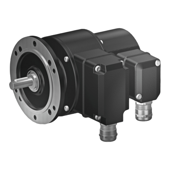
- Page 1 Montage- und Betriebsanleitung Installation and operating instructions POG 90 + FSL Kombination Combination...
-
Page 2: Table Of Contents
Montage / Mounting Inhaltsverzeichnis Inhaltsverzeichnis Allgemeine Hinweise ..............................Sicherheitshinweise ..............................Vorbereitung ..................................3.1 Lieferumfang ................................ 3.2 zur Montage erforderlich bzw. empfohlen (nicht im Lieferumfang enthalten) ....Montage ....................................4.1 Schritt 1 ................................... 4.2 Schritt 2 ................................... 4.3 Schritt 3 ................................... 4.4 Schritt 4 ... - Page 3 Montage / Mounting Table of contents Table of contents General notes ................................... Security indications ..............................Preparation ..................................3.1 Scope of delivery ............................... 3.2 required resp. recommended for mounting (not included in scope of delivery) ....Mounting ....................................4.1 Step 1 ..................................4.2 Step 2 ..................................4.3 Step 3 ..................................4.4 ...
-
Page 4: Allgemeine Hinweise
Allgemeine Hinweise Allgemeine Hinweise 1.1 Die Kombination POG 90 + FSL ist ein opto-elektronisches Präzisionsmessgerät, das mit Sorgfalt nur von technisch qualifiziertem Personal gehandhabt werden darf. 1.2 Die zu erwartende Lebensdauer des Gerätes hängt von den Kugellagern ab, die mit einer Dauerschmierung ausgestattet sind. 1.3 Der Lagertemperaturbereich des Gerätes liegt zwischen -15 °C bis +70 °C. 1.4 Der Betriebstemperaturbereich des Gerätes liegt zwischen -20 °C bis +85 °C, am Gehäuse gemessen. 1.5 EG Konformitätserklärung gemäß Richtlinie 89/336/EWG Artikel 10 - sowie Anhang 1 (EMV-Richtlinie). 1.6 Wir gewähren 2 Jahre Gewährleistung im Rahmen der Bedingungen des Zentralverbandes der ... -
Page 5: General Notes
General notes General notes 1.1 The combination POG 90 + FSL is an opto electronic precision measurement device which must be handled with care by skilled personnel only. 1.2 The expected operating life of the device depends on the ball bearings, which are equipped with a permanent lubrication. 1.3 The storage temperature range of the device is between -15 °C and +70 °C. 1.4 The operating temperature range of the device is between -20 °C and +85 °C, measured at the housing. 1.5 ... -
Page 6: Sicherheitshinweise
Sicherheitshinweise Sicherheitshinweise Verletzungsgefahr durch rotierende Wellen Haare und Kleidungsstücke können von rotierenden Wellen erfasst werden. Vor allen Arbeiten alle Betriebsspannungen ausschalten und Maschinen stillsetzen. • Zerstörungsgefahr durch elektrostatische Aufladung Die elektronischen Bauteile in der Kombination sind empfindlich gegen hohe Spannungen. Steckkontakte und elektronische Komponenten nicht berühren. • Ausgangsklemmen vor Fremdspannungen schützen. • Max. Betriebsspannung nicht überschreiten. • Zerstörungsgefahr durch mechanische Überlastung Eine starre Befestigung kann zu Überlastung durch Zwangskräfte führen. Die Beweglichkeit der Kombination niemals einschränken. Unbedingt die Montagehinweise • beachten. -
Page 7: Security Indications
Security indications Security indications Risk of injury due to rotating shafts Hair and clothes may become tangled in rotating shafts. Before all work switch off all operating voltages and ensure machinery is stationary. • Risk of destruction due to electrostatic charge Electronic parts contained in the combination are sensitive to high voltages. Do not touch plug contacts or electronic components. • Protect output terminals against external voltages. • Do not exceed max. operating voltage. • Risk of destruction due to mechanical overload Rigid mounting may give rise to constraining forces. Never restrict the freedom of movement of the combination. The installation instructions must •... -
Page 8: Vorbereitung
Vorbereitung / Preparation Vorbereitung Preparation Lieferumfang Scope of delivery EURO-Flansch EURO flange Gehäuse POG 90 Housing POG 90 Gehäuse FSL Housing FSL Vollwelle mit Passfeder Solid shaft with key Klemmenkastendeckel POG 90 Terminal box cover POG 90 Anschlussplatine mit Anschlussklemmen POG 90 Connecting board with connecting terminal POG 90 (siehe Abschnitt 4.10 und 6.1) (see section 4.10 and 6.1) SUB-D Stecker am Gebergehäuse POG 90 SUB D connectors (male) on the encoder housing Kabelverschraubung M20x1,5 für Kabel ∅5-13 mm Screwed gland M20x1.5 for cable ∅5-13 mm Klemmenkastendeckel FSL Terminal box cover FSL Anschlussklemmen FSL (s. Abschnitt 4.13 und 6.4) Connecting terminal FSL (s. section 4.13 and 6.4) Kabelverschraubung M20x1,5 für Kabel ∅5-9 mm Screwed gland M20x1.5 for cable ∅5-9 mm MB154.1 5 pog90-fsl_mb (08A1) ... -
Page 9: Zur Montage Erforderlich Bzw. Empfohlen (Nicht Im Lieferumfang Enthalten)
Vorbereitung / Preparation zur Montage erforderlich bzw. empfohlen required resp. recommended for mounting (nicht im Lieferumfang enthalten) (not included in scope of delivery) Anbauvorrichtung mit Befestigungsschrauben Installation fitting with fixing screws Federscheiben-Kupplung K 35 Spring disk coupling K 35 (als Zubehör erhältlich) (available as accessory) Anschlusskabel HEK 8 Connecting cable HEK 8 (als Zubehör erhältlich, siehe Abschnitt 6.3) (available as accessory, see section 6.3) Anschlusskabel für FSL Connecting cable FSL MB154.1 pog90-fsl_mb (08A1) ... -
Page 10: Montage
Montage / Mounting Montage Mounting Schritt 1 Step 1 zul. Anzugsmoment Max tightening torque = 2-3 Nm Schritt 2 Step 2 1), 2) Motorwelle einfetten! Lubricate motor shaft! Sollte die Rundlaufabweichung mehr If the radial run-out is more than als 0,03 mm betragen, so kontaktieren 0.03 mm, please contact our hotline: Sie bitte unsere Hotline: +49 (0)30/69003-111... -
Page 11: Schritt 3
Montage / Mounting Schritt 3 Step 3 Schritt 4 Step 4 zul. Anzugsmoment Max tightening torque = 2-3 Nm MB154.1 pog90-fsl_mb (08A1) ... -
Page 12: Max. Zulässige Anbaufehler Unter Verwendung Der Baumer Hübner Federscheiben-Kupplung K 35
Montage / Mounting Max. zulässige Anbaufehler Max. permissible mounting tolerance unter Verwendung der Baumer Hübner when the Baumer Hübner Federscheiben-Kupplung K 35 K 35 spring disk coupling is used Kombinationen mit Vollwelle sollten Combinations with a solid shaft should be unter Verwendung der Baumer Hübner driven through the Baumer Hübner K 35 Federscheiben-Kupplung K 35 (Zubehör) spring disk coupling (accessory), that can ... -
Page 13: Anbauhinweis
Wasserein- connection is not directly exposed to tritt ausgesetzt ist. water. Schritt 5 - Klemmenkasten POG 90 Step 5 - Terminal box POG 90 MB154.1 pog90-fsl_mb (08A1) ... -
Page 14: Schritt 6 - Klemmenkasten Pog 90
Montage / Mounting Schritt 6 - Klemmenkasten POG 90 Step 6 - Terminal box POG 90 Schritt 7 - Klemmenkasten POG 90 Step 7 - Terminal box POG 90 MB154.1 11 pog90-fsl_mb (08A1) ... -
Page 15: Schritt 8 - Klemmenkasten Pog 90
Montage / Mounting 4.10 Schritt 8 - Klemmenkasten POG 90 4.10 Step 8 - Terminal box POG 90 Kabelschirm Cable shield Ansicht siehe Abschnitt 6.1 View iew see section 6.1 4.11 Schritt 9 - Klemmenkasten POG 90 4.11 Step 9 - Terminal box POG 90 MB154.1 ... -
Page 16: Schritt 10 - Klemmenkasten Pog 90
Montage / Mounting 4.12 Schritt 10 - Klemmenkasten POG 90 4.12 Step 10 - Terminal box POG 90 Um 180° wendbarer Klemmenkasten Reversible terminal box cover 4.13 Schritt 11 - Klemmenkasten FSL 4.13 Step 11 - Terminal box FSL MB154.1 13 pog90-fsl_mb (08A1) ... -
Page 17: Schritt 12 - Klemmenkasten Fsl
Montage - Maßzeichnung / Mounting - Dimension drawing 4.14 Schritt 12 - Klemmenkasten FSL 4.14 Step 12 - Terminal box FSL Ansicht Um 180° wendbarer siehe Abschnitt 6.4 Klemmenkasten View iew Reversible see section 6.4 terminal box cover Maßzeichnung Dimension drawing Drehrichtung positiv Positive direction of rotation All dimensions in millimeters (unless otherwise stated) MB154.1 ... -
Page 18: Elektrischer Anschluss
Elektrischer Anschluss / Electrical connection Elektrischer Anschluss Electrical connection Klemmenbelegung POG 90 Terminal assignment POG 90 6.1.1 POG 90 DN … 6.1.1 POG 90 DN … max. 1,5 mm Ansicht Y max. AWG 16 Anschlussklemmen POG 90 siehe Abschnitt 4.10 View Y Connecting terminal POG 90 see section 4.10 Zwischen und besteht keine Verbindung. There is no connection between and 6.1.2 POG 90 DN …... -
Page 19: Ausgangssignale Pog 90
Elektrischer Anschluss / Electrical connection Ausgangssignale POG 90 Output signals POG 90 1 Signalfolge bei positiver Drehrichtung. (siehe Abschnitt 5) 1 Sequence for positive direction of rotation. (see section 5) 1 90° nur bei Ausführung mit invertierten Signalen only for versions with inverted signals Kabel HEK 8 (Zubehör) Cable HEK 8 (accessory) Es wird empfohlen, das Baumer Hübner Baumer Hübner cable HEK 8 is recom- Kabel HEK 8 ... -
Page 20: Klemmenbelegung Fsl
Elektrischer Anschluss - Demontage / Electrical connection - Dismounting Klemmenbelegung FSL Terminal assignment FSL Ansicht Z Anschlussklemmen FSL siehe Abschnitt 4.13 View Z Schließer Connecting terminal FSL Make contact see section 4.13 Schaltleistung Switching capacity Öffner 6 A / ~ 200 V Break contact Demontage Dismounting Schritt 1 Step 1 MB154.1 17 pog90-fsl_mb (08A1) ... - Page 21 Demontage / Dismounting Schritt 2 Step 2 Schritt 3 Step 3 MB154.1 pog90-fsl_mb (08A1) ...
- Page 22 Demontage / Dismounting Schritt 4 Step 4 Schritt 5 Step 5 MB154.1 19 pog90-fsl_mb (08A1) ...
-
Page 23: Zubehör
Zubehör / Accessories Zubehör Accessories Federscheiben-Kupplung Spring disk coupling • • K 35 K 35 Anschlusskabel Connecting cable • • HEK 8 HEK 8 Frequenz-Analog-Wandler: Frequency-analogue converter: • • HEAG 121 P HEAG 121 P Digital-Konverter: Digital converters: • • HEAG 151 - HEAG 154 HEAG 151 - HEAG 154 LWL-Übertrager: Fiber optic links: • • HEAG 171 - HEAG 176 HEAG 171 - HEAG 176 Digitaler Drehzahlschalter: Digital speed switch: • • DS 93 DS 93 MB154.1 ... -
Page 24: Technische Daten
Montage / Mounting Technische Daten Technische Daten Technische Daten - Kombination POG 90 + FSL 1,25 . n max. Drehzahl (mechanisch): min (n = Schaltdrehzahl, siehe Abschnitt 9.3) • 15 . 10 max. Drehzahl (elektronisch): • (z = siehe Abschnitt 9.2) z Trägheitsmoment: ≈ 60 kgcm • Schwingungsfestigkeit: ≤ 100 m/s ≈ 10 g IEC 60068-2-6 ... -
Page 25: Technische Daten - Fliehkraftschalter Fsl
Technische Daten - Fliehkraftschalter FSL Schaltdrehzahl n : 850 ... 4.900 min (je nach Bestellung) • Schaltgenauigkeit bei geringer Beschleunigung : ±4 % • Schaltgenauigkeit bei hoher Beschleunigung : ≤ +20 % • Schaltdifferenz Rechts-/Linkslauf: ≈ 3 % • ≈ 40 % Drehzahl-Hysterese: • Schaltvermögen: 6 A / 230 V AC • 1 A / 125 V DC eingestellt im Werk bei Drehzahlanstieg ∆n = 2 min /s Drehzahlanstieg: ∆n = 2 min /s ... -
Page 26: Technical Data
Technical data Technical data Technical data - Combination POG 90 + FSL 1,25 . n Maximum speed (mechanical): rpm (n = switching speed, see section 9.3) • 15 . 10 Maximum speed (electronic): • rpm (z = see section 9.2) z Moment of inertia: ≈ 60 kgcm • Vibration resistance: ≤ 100 m/s ≈ 10 g IEC 60068-2-6 • (10 Hz ... 2 kHz) Shock resistance (11 ms): ... -
Page 27: Technical Data - Mechanical Centrifugal Switch Fsl
Technical data - Mechanical centrifugal switch FSL Switching speed n : 850 ... 4,900 rpm (as precised on order) 1) • Switching speed at low acceleration : ±4 % • Switching speed at high acceleration : ≤ +20 % • Switching tolerance cw to cww: ≈ 3 % • ≈ 40 % Speed hysterisis: • Switch capacity: 6 A / 230 V AC • 1 A / 125 V DC adjusted by the manufacturer at speed rise ∆n = 2 rpm/s Speed rise: ∆n = 2 rpm/s ... - Page 28 Baumer Hübner GmbH P.O. Box 61 02 71 · D-10924 Berlin, Germany Phone: +49 (0)30/69003-0 · Fax: +49 (0)30/69003-104 Technische Änderungen vorbehalten. info@baumerhuebner.com · www.baumerhuebner.com Technical modifications reserved. MB154.1 pog90-fsl_mb (08A1 - 17.01.2008) ...
Need help?
Do you have a question about the POG 90 and is the answer not in the manual?
Questions and answers