
Related Manuals for Elsema 240S1 Series


Summary of Contents for Elsema 240S1 Series
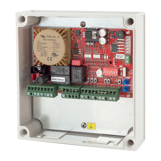
- Page 1 VERSION 3 240S1 240S2 Controller Card for 240VAC Motors used on Light Commercial Doors, Industrial Roller Shutters, Sectional Doors, Garage Doors, Sliding Doors and Swing Gates...
-
Page 2: Important Warning And Safety Instructions
Elsema Pty Ltd shall not be liable for any injury, damage, cost, expense or any claim whatsoever to any person or property which may result from improper use or installation of this product. -
Page 3: Part Numbers
The company will not accept liability for failure to comply with the figures or estimates due to the nature of variable conditions affecting for example Radio Remote Controls. Please keep this setup instruction for future reference. www.elsema.com... -
Page 4: Block Diagram
Block Diagram 240S1 Controller Card for 240VAC Motors... - Page 5 Open, Close LEDs Indicates Opening or Closing cycle. Enter button Used to change features in programming mode. Used to connect Elsema’s receivers to operate the control card with a remote control. Use Receiver Elsema’s Pentacode series. Antenna Used to connect an external antenna for the plug in receiver.
- Page 6 Block Diagram 240S2 FUSE Earth Active Neutral Open Close Neutral Motor Capacitor Motor Capacitor Output NO Output C Open Limit Common Close Limit Push Button Open Only Close Only Common Common Stop PED Access Photo Beam DC Output + DC Output - Controller Card for 240VAC Motors...
- Page 7 Used to connect a photo electric beam. Factory Default is Normally Closed input. User can change to Photo Electric Beam Normally Open. DC Output 24VDC / 150mA. Use to supply accessories. (Use Elsema Reg12 to convert this output to 12VDC) Common Common terminal for Key Switch (NC Type) Auto Auto terminal for key switch.
-
Page 8: Setup Instructions
Setup Instructions Electrical Wiring Always switch off power before doing any wiring. Make sure that all the wiring is completed and that the motor is connected to the control DANGER Mains card. Recommended wire strip length should be 10mm for all connections to voltage the plug in terminal blocks. - Page 9 The press and hold and latching functions can be changed by following the steps and table below: 1. Set dip switch 7 and 8 “ON” and 1 to 6 “OFF” 2. Set the mode switch to program mode 1 www.elsema.com...
- Page 10 3. Set dip switch 1, 2, 3 and 4 as shown in the table below Dip switch 1 Dip switch 2 Dip switch 3 Dip switch 4 On = Press and Hold Open Button Off = Latching On = Press and Hold Close Button Off = Latching On = Press and Hold...
- Page 11 6. Set mode switch to Run status LED’s are indicating the correct status of the limit switches. LED “ON” means limit switch is activated. Limit switch status LED's Relay 2 3 4 5 Normally Closed User can change to Normally Open www.elsema.com...
- Page 12 Supply and Motor Wiring Diagram Connect the supply and 240VAC motor as shown in the diagram below. If the motor does not have an internal starting capacitor the board has provision to connect the capacitor. Warning Make sure that the mains power is always switched off before doing any wiring. DANGER Mains voltage...
- Page 13 9. Release the push button or remote when the door/gate reaches the fully close position 10. Press the Enter button, the buzzer will beep for 2 sec to indicate learning is successful 11. Set mode switch to Run Mode or change dip switch to exit learn mode www.elsema.com...
- Page 14 Slow Speed In order to use slow speed, travel time has to be setup. The slow speed can be adjusted anytime during setup or in normal run mode. Slow speed can be adjusted independently for open and close. If slow speed is not required, turn the blue pots fully clockwise.
- Page 15 3. Set dip switch 1 to 4 and 6, 7, 8 to “OFF” 3. Press button “A” for 30 seconds, “C” for 10 seconds or “E” for 2 seconds 4. Switch off all dip switches 5. Set mode switch to Run mode www.elsema.com...
-
Page 16: Dip Switch Functions
Dip Switch Functions Feature Dip Switch settings Description Dip switch 1 “ON” Auto close is a feature that automatically closes the gate/door after a Auto Close preset time has counted down to zero. Adjust the auto close trimpot to change time between 3 – 60 seconds. 1 2 3 4 5 6 7 8 1 2 3 4 5 6 7 8 Dip switch 2 “ON”... -
Page 17: Key Switch
2. Set dip switch 1 to 5 “OFF” 3. Set mode switch to program mode 2, the run LED will turn orange 4. Press Enter button for 5 seconds the buzzer will beep to confirm the resetting was successful 5. Set mode switch to Run mode. www.elsema.com... - Page 18 PentaCODE Series ® Photoelectric beam The photoelectric beam is usually used as a safety device to control automatic gates and doors. Elsema has several types of photoelectric beams including retro-reflective and through beam with IP-66 ratings for outdoor use. PE24...
- Page 19 The digital technology of the loop detector enables the equipment to sense a change in the inductance of the loop as soon as it detects the metal object in its path. MD12-1 (1 Channel) MD12-2 (2 Channel) MD2010 LD30-12 Also available with 240VAC Supply Connection www.elsema.com...
- Page 20 ELSEmA PTy LTD 31 Tarlington Place Smithfield NSW 2164 Australia 02 9609 4668 02 9725 2663 www.elsema.com...
Need help?
Do you have a question about the 240S1 Series and is the answer not in the manual?
Questions and answers