
Related Manuals for GEM 127 Series


Summary of Contents for GEM 127 Series
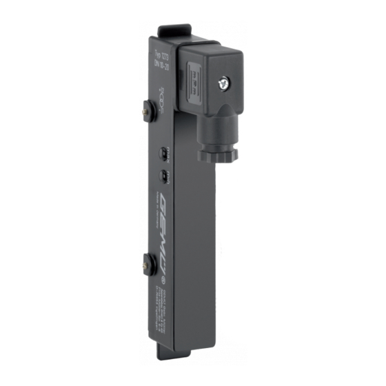
- Page 1 GEMÜ 127x Instrument sensor Operating instructions further information webcode: GW-127x...
- Page 2 All rights including copyrights or industrial property rights are expressly reserved. Keep the document for future reference. © GEMÜ Gebr. Müller Apparatebau GmbH & Co. KG 22.10.2019 GEMÜ 127x 2 / 20 www.gemu-group.com...
-
Page 3: Table Of Contents
Product label ............5 Correct use ..............6 Product line ............... 7 Availability ..............8 Order data GEMÜ 1270, 1272 ........9 Order data GEMÜ 1271, 1273 ........10 10 Technical data ............11 10.1 Mechanical data ..........11 10.2 Electrical data ............. -
Page 4: General Information
Imminent danger! ▶ Non-observance can cause death or severe injury. WARNING Potentially dangerous situation! ▶ Non-observance can cause death or severe injury. CAUTION Potentially dangerous situation! ▶ Non-observance can cause moderate to light injury. GEMÜ 127x 4 / 20 www.gemu-group.com... -
Page 5: Safety Information
2. Do not paint the bolts and plastic parts of the product. 4. Do not store solvents, chemicals, acids, fuels or similar 3. Carry out installation and commissioning using trained fluids in the same room as GEMÜ products and their personnel. spare parts. -
Page 6: Function
The instrument sensor is equipped with a reed contact chain. This enables reading out the float position. 4.2.1 GEMÜ 1270 / 1271 function The GEMÜ 1270 / 1271 instrument sensors output the meas- Item number Traceability number Serial number... -
Page 7: Product Line
6 Product line 6 Product line GEMÜ 1270 GEMÜ 1271 GEMÜ 1272 GEMÜ 1273 Metering 118 / 147 118 / 125 length [mm] Number of switch 55 / 100 35 / 43 55 / 100 35 / 43 points Distance of reed 4.25 / 2.30... -
Page 8: Availability
7 Availability 7 Availability GEMÜ 1270, 1272 Type Order code Flowmeter series 800 20 - 65 20 - 65 20 - 65 20 - 65 20 - 65 20 - 65 20 - 65 20 - 65 20 - 65 GEMÜ... -
Page 9: Order Data Gemü 1270, 1272
8 Order data GEMÜ 1270, 1272 8 Order data GEMÜ 1270, 1272 Order codes 1 Type Code 4 Series Code Instrument sensor for variable area flowmeter 1270 Series 800, DN 20 - DN 65 Instrument sensor for variable area flowmeter... -
Page 10: Order Data Gemü 1271, 1273
Instrument sensor 1273 5 Resolution Code for variable area flowmeter 35 contacts, 2 Fieldbus Code GEMÜ 865, 867, 880, 885 DN 10 - DN 20 43 contacts, without GEMÜ 865, 867, 880, 885 DN 25 3 Accessory Code 100 contacts Accessory... -
Page 11: Technical Data
3,50 mm GEMÜ 1273000Z2501 125 mm 3,50 mm 10.2 Electrical data Supply voltage: GEMÜ 1270, 1271: max. 24 V DC GEMÜ 1272, 1273: 11 V DC + 0.02 A x load resistor (Ω) 40 V DC For values see diagram max. -
Page 12: Dimensions
11 Dimensions 11 Dimensions GEMÜ 1270, 1272 GEMÜ 1271, 1273 DN 10 - 20 DN 25 23,2 23,2 17,4 59,5 32,8 32,8 Dimensions in mm 12 / 20 GEMÜ 127x www.gemu-group.com... -
Page 13: Assembly
2 must be Fig. 3: Minimum distance between instrument sensors aligned with the upper edge of the dovetail 1. 4. Fix the position with the locking screws 3. ð The instrument sensor is assembled. www.gemu-group.com 13 / 20 GEMÜ 127x... -
Page 14: Electrical Connection
13 Electrical connection 13 Electrical connection 13.2 GEMÜ 1270 / 1271 electrical connection DANGER Risk of electric shock ▶ Risk of injury or death (if operating voltage is higher than safe extra low voltage). ▶ Electric shock can cause severe burns and fatal injury. -
Page 15: Commissioning
80 % (= 16.8 mA) volumetric flow, in order to com- Only the spare parts specified below must be replaced. ● pensate the difference between the linear output signal and The device must only be repaired by GEMÜ. ● the non-linear scaling of the flowmeters. Preventive maintenance/cleaning is recommended depend- ing on the operating conditions. -
Page 16: Troubleshooting
When several flowmeters are installed Minimum distance between instrument Ensure 150 mm minimum distance next to each other, the instrument sensors too low between the instrument sensors sensors may interfere with each other and send false signals 16 / 20 GEMÜ 127x www.gemu-group.com... -
Page 17: Disposal
Returned goods can be processed only when this note is completed. If no return delivery note is included with the product, GEMÜ cannot process credits or repair work but will dispose of the goods at the operator's expense. -
Page 18: Declaration Of Conformity According To 2014/35/Eu (Low Voltage Directive)
20 Declaration of conformity according to 2014/35/EU (Low Voltage Directive) EU Declaration of Conformity in accordance with 2014/35/EU (Low Voltage Directive) GEMÜ Gebr. Müller Apparatebau GmbH & Co. KG Fritz-Müller-Straße 6-8 74653 Ingelfingen-Criesbach, Germany declare that the product listed below complies with the safety requirements of the Low Voltage Directive 2014/35/EU. - Page 19 19 / 20 GEMÜ 127x www.gemu-group.com...
- Page 20 GEMÜ Gebr. Müller Apparatebau GmbH & Co. KG Subject to alteration Fritz-Müller-Straße 6-8, 74653 Ingelfingen-Criesbach, *88659290* Germany 10.2019 | 88659290 Phone +49 (0)7940 123-0 · info@gemue.de www.gemu-group.com...
Need help?
Do you have a question about the 127 Series and is the answer not in the manual?
Questions and answers