Table of Contents
Advertisement
Quick Links
Advertisement
Table of Contents

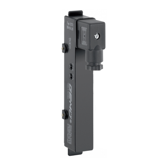
Summary of Contents for GEM 127 Series
- Page 1 GEMÜ 127x Instrument sensor Operating instructions...
- Page 2 All rights including copyrights or industrial property rights are expressly reserved. Keep the document for future reference. © GEMÜ Gebr. Müller Apparatebau GmbH & Co. KG 02.08.2021 GEMÜ 127x 2 / 20 www.gemu-group.com...
-
Page 3: Table Of Contents
GEMÜ 1272 / 1273 function .... GEMÜ CONEXO ..........Product label ..........5 Correct use ............6 Order data GEMÜ 1270, 1272 ....... 7 Order data GEMÜ 1271, 1273 ....... 8 Technical data ............. Mechanical data ..........Electrical data .......... -
Page 4: General Information
Imminent danger! ▶ Non-observance can cause death or severe injury. WARNING Potentially dangerous situation! ▶ Non-observance can cause death or severe injury. CAUTION Potentially dangerous situation! ▶ Non-observance can cause moderate to light injury. GEMÜ 127x 4 / 20 www.gemu-group.com... -
Page 5: Safety Information
3. Carry out installation and commissioning using trained 4. Do not store solvents, chemicals, acids, fuels or similar personnel. fluids in the same room as GEMÜ products and their spare 4. Provide adequate training for installation and operating parts. personnel. -
Page 6: Product Description
This enables reading out the float position. Item Name 4.3.1 GEMÜ 1270 / 1271 function Plug The GEMÜ 1270 / 1271 instrument sensors output the meas- LED display ured values as a voltage signal via a voltage divider (Rg = 10 Instrument sensor kΩ). -
Page 7: Product Label
The products must: proves the "installation qualification" process, but also makes • only be used for measuring the flowmeters of the GEMÜ the maintenance process much more transparent and easier 800, GEMÜ 840 and GEMÜ 850 series. to document. The app actively guides the maintenance techni- cian through the maintenance schedule and directly provides •... -
Page 8: Order Data Gemü 1270, 1272
6 Order data GEMÜ 1270, 1272 6 Order data GEMÜ 1270, 1272 Order codes 1 Type Code 4 Series Code Instrument sensor for variable area flowmeter 1270 Series 800, DN 20 - DN 65 Instrument sensor for variable area flowmeter... -
Page 9: Order Data Gemü 1271, 1273
Instrument sensor 1273 5 Resolution Code for variable area flowmeter 35 contacts, 2 Fieldbus Code GEMÜ 865, 867, 880, 885 DN 10 - DN 20 43 contacts, without GEMÜ 865, 867, 880, 885 DN 25 3 Accessory Code 100 contacts Accessory... -
Page 10: Technical Data
3,50 mm GEMÜ 1273000Z2501 125 mm 3,50 mm 8.2 Electrical data Supply voltage: GEMÜ 1270, 1271: max. 24 V DC GEMÜ 1272, 1273: 11 V DC + 0.02 A x load resistor (Ω) 40 V DC For values see diagram max. -
Page 11: Dimensions
9 Dimensions 9 Dimensions GEMÜ 1270, 1272 GEMÜ 1271, 1273 DN 10 - 20 DN 25 23,2 23,2 17,4 59,5 32,8 32,8 Dimensions in mm www.gemu-group.com 11 / 20 GEMÜ 127x... -
Page 12: Assembly
2 must be aligned with the upper edge of the dovetail 1. 4. Fix the position with the locking screws 3. ð The instrument sensor is assembled. GEMÜ 127x 12 / 20 www.gemu-group.com... -
Page 13: Electrical Connection
11 Electrical connection 11 Electrical connection 11.2 GEMÜ 1270 / 1271 electrical connection DANGER Risk of electric shock ▶ Risk of injury or death (if operating voltage is higher than safe extra low voltage). ▶ Electric shock can cause severe burns and fatal injury. -
Page 14: Commissioning
12.1.1 Resetting the product To carry out a reset of the product, press the 1 "min" and 3 "max" keys simultaneously. The reset is completed when the status LED lights up red. GEMÜ 127x 14 / 20 www.gemu-group.com... -
Page 15: Maintenance
▶ Damage to the product. ▶ Manufacturer liability and guarantee will be void. Only the spare parts specified below must be replaced. ● The device must only be repaired by GEMÜ. ● Preventive maintenance/cleaning is recommended depending on the operating conditions. -
Page 16: Troubleshooting
Ensure that the float is within the range of the instrument sensor Product not ready for opera- Initialize product tion and not initialized Output 21 mA (standard range: 4–20 mA) LED conditions lit (on) flashes GEMÜ 127x 16 / 20 www.gemu-group.com... -
Page 17: Disposal
Returned goods can be processed only when this note is completed. If no return delivery note is included with the product, GEMÜ cannot process credits or repair work but will dispose of the goods at the operator's expense. - Page 18 GEMÜ 127x 18 / 20 www.gemu-group.com...
- Page 19 19 / 20 GEMÜ 127x...
- Page 20 Subject to alteration GEMÜ Gebr. Müller Apparatebau GmbH & Co. KG *88659290* Fritz-Müller-Straße 6-8, 74653 Ingelfingen-Criesbach, Germany 08.2021 | 88659290 Phone +49 (0) 7940 1230 · info@gemue.de www.gemu-group.com...


Need help?
Do you have a question about the 127 Series and is the answer not in the manual?
Questions and answers