Table of Contents
Advertisement
Quick Links
®
Advanced Test Equipment Rentals
www.atecorp.com 800-404-ATEC (2832)
AVTM21- 415Ja
Rev A
June 2005
15 kV Megohmmeter
Test Set
Catalog No. 210415 Series
High-Voltage Equipment
Read the entire manual before operating.
Aparato de Alto Voltaje
Antes de operar este producto lea este manual enteramente.
2621 Van Buren Avenue
Norristown, PA 19403
1-800-723-2861 ext. 8578
megger.com
Advertisement
Table of Contents

Related Manuals for Megger ATEC 210415 Series


Summary of Contents for Megger ATEC 210415 Series
- Page 1 15 kV Megohmmeter Test Set Catalog No. 210415 Series High-Voltage Equipment Read the entire manual before operating. Aparato de Alto Voltaje Antes de operar este producto lea este manual enteramente. 2621 Van Buren Avenue Norristown, PA 19403 1-800-723-2861 ext. 8578 megger.com...
- Page 2 15 kV Megohmmeter Test Set Catalog No. 210415 Series...
- Page 3 If the product or its individual instruments are used for purposes other than those specified herein, confirmation of their validity and suitability must be obtained from Megger. Specifications are subject to change without notice. Valley Forge Corporate Center 2621 Van Buren Avenue...
-
Page 4: Table Of Contents
Table of Contents 1 INTRODUCTION..................1 2 SAFETY PRECAUTIONS...............3 3 RECEIVING INSTRUCTIONS.............5 4 SPECIFICATIONS..................7 5 DESCRIPTION ..................13 6 CONTROL & CONNECTOR IDENTIFICATION...... 17 7 SETTING UP................... 19 Preparation ....................19 Selection of Location................19 Clearances....................21 8 OPERATION................... 27 Test Procedure..................27 Breakdown of Test Item .................28 Normal Shutdown Procedure ..............29 Interrupting a Test ...................29 9 OPERATION NOTES................ - Page 5 10 APPLICATION NOTES..............41 Theory of Insulation Testing ..............41 Applying the Test Set................42 Measuring an Ungrounded Test Item........... 43 Generalized Combined 2 and 3 Terminal Measurement....45 11 ROUTINE MAINTENANCE............47 Introduction....................47 Inspection and Maintenance Procedure..........47 12 TROUBLESHOOTING AND REPAIR..........51 General ......................
- Page 6 List of Figures Figure 1: 15 kV Megohmmeter Test Set, Catalog No. 210415....2 Figure 2: Schematic Diagram of the 15 kV Megohmmeter....16 Figure 3A: View of the 15 kV Megohmmeter Test Set......17 Figure 3B: View of the 15 kV Megohmmeter Test Set......18 Figure 4: Testing in a Substation..............
- Page 7 List of Tables TABLE 1: Minimum Air Clearances............21 TABLE 2: Two & Three Terminal Measurement Connection Schedule..............44 TABLE 3: Trouble Location Chart ............63 AVTM21-415Ja Rev. A June 2005...
-
Page 8: Introduction
When these data are recorded on graph paper such as Megger Ki1ovo1t- Megohm Paper (Catalog No. 220000), the shape of the curve made by connecting the plotted points will aid in evaluating the condition of the insulation system. -
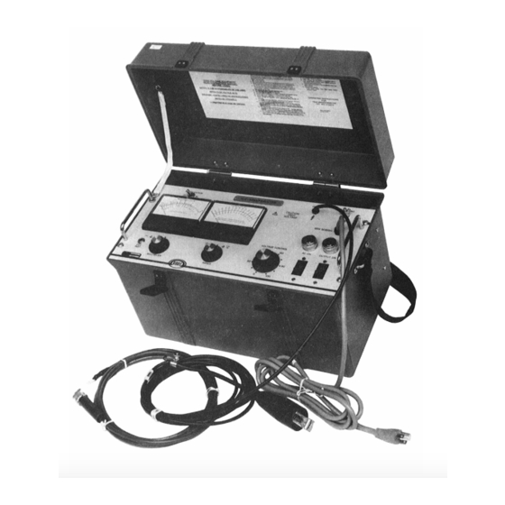
Page 9: Figure 1: 15 Kv Megohmmeter Test Set, Catalog No. 210415
Figure 1: 15 kV Megohmmeter Test Set, Catalog No. 210415 AVTM21-415Ja Rev. A June 2005... -
Page 10: Safety Precautions
SAFETY PRECAUTIONS SAFETY IS THE RESPONSIBILITY OF THE USER. LA SEGURIDAD ES LA RESPONSABILIDAD DEL OPERADOR. The Test Set and the equipment to which it is connected are a source of high-voltage electrical energy. All persons performing or assisting in the tests must use all practical safety precautions to prevent contact with energized parts of the test equipment and associated circuits. - Page 11 As a routine safety procedure, however, some users require that rubber gloves be worn, not only when making connections to the high-voltage terminals, but also when manipulating controls. Megger considers this an excellent safety practice. PACEMAKERS High voltage discharges and other sources of strong electric or magnetic fields may interfere with the proper functioning of heart pacemakers.
-
Page 12: Receiving Instructions
Examine the instruments for damage received in transit. If any damage is discovered, file a claim with the carrier at once and notify Megger or its nearest authorized sales representative, giving a detailed description of the damage observed. This instrument has been thoroughly tested and inspected to meet rigid inspection specifications before being shipped. - Page 13 AVTM21-415Ja Rev. A June 2005...
-
Page 14: Specifications
SPECIFICATIONS POWER SUPPLY: Catalog No. 210415 Voltage (rms): 105-130 Volts Recommended NEC 15 Ampere, 120 Volts, single-phase Source: branch circuit (3 wire: line, neutral and ground). Current (rms): 1.5 Amps, maximum continuous. Frequency: 60 Hz, full rating. 50 Hz, reduced rating. Basis of Rated 120 Volt 60 Hz supply with stabilizer out. - Page 15 OUTPUT TEST 0-15 kV dc, negative with respect to ground. VOLTAGE: OUTPUT CURRENT: With Stabilizer Out 2 mA continuous; 5 mA for 12 minutes. at 60 Hz: at 50 Hz: 1.67 mA continuous; 4.17 mA for 12 minutes. With Stabilizer In at At 15 kV, 50 µA continuous.
- Page 16 SPECIFICATIONS MEGOHMMETER SPAN, MEGOHMS VOLTMETER VOLTAGE RANGE RANGE RANGE RANGE RANGE SWITCH SWITCH SWITCH SWITCH SETTING at x 1 at x 10 at x 100 at x 1K 2-200 20-2000 200- 2000- 20,000 200,000 1-100 10-1000 100- 1000- 10,000 100,000 EITHER up to up to...
- Page 17 CABLES AND CONNECTORS Input Cable: Attached; 5 feet (1.5 meters), 3-wire with plug. Output Cable: Attached; shielded with GUARD terminal, high voltage clip and boot; 15 feet (4.6 meters) long. Ground Cable: Separate, 10 feet (3.3 meters) with positive action clamp at outboard end.
- Page 18 SPECIFICATIONS ENVIRONMENT Temperature: 0°F (-17.7°C) to 122°F (50°C) maximum operating. Altitude: 10,000 feet, (3,048 meters) maximum operating. Relative Humidity: Non-condensing conditions. Shock and Vibration: Will withstand normal shock and vibration encountered in field use and transportation. PROTECTIVE FEATURES § Dual overload protection for all overload conditions by two separate circuit breakers.
- Page 19 AVTM21-415Ja Rev. A June 2005...
-
Page 20: Description
DESCRIPTION GENERAL The portable Megohmmeter Test Set measures the electrical quantities of applied voltage and resistance of the apparatus to which it is connected. Designed for field or shop use, the complete Test Set (including all leads) is housed in a rugged structural foam, polycarbonate case that includes a sturdy protective lid and carrying strap. - Page 21 of the power supply is the high voltage output and is connected to the center conductor of output cable W101. The positive terminal of the power supply is used as a guard and is connected to the shield of the output cable with a terminal at the outboard end.
- Page 22 DESCRIPTION used as the power-on switch. When power is available and CB1 is closed the green ac ON lamp comes on. The path is interrupted by the contact of K2. Moving the voltage control T1 to zero closes the contacts of the zero start switch. This action applies the line voltage to the coil of K2 and ultimately to T1.
-
Page 23: Figure 2: Schematic Diagram Of The 15 Kv Megohmmeter
Figure 2: Schematic Diagram of the 15 kV Megohmmeter AVTM21-415Ja Rev. A June 2005... -
Page 24: Control & Connector Identification
CONTROL & CONNECTOR IDENTIFICATION Guard Terminal 7. Carrying Strap 2. & 23. Output Cable 8. Removable Case Cover High Voltage Terminal 26. Location of -47 Option Step-Down Transformer Ground Cable 27. Lead Storage 5. & 25. Power Cord Instruction Card Figure 3A: View of the 15 kV Megohmmeter Test Set AVTM21-415Ja Rev. -
Page 25: Figure 3B: View Of The 15 Kv Megohmmeter Test Set
Figure 3B: View of the 15 kV Megohmmeter Test Set External Instrument Jack 17. 15 kV Voltmeter Calibrator 10. Megohmmeter Calibrator 18. Voltage Control 11. Megohm Multiplier Selector 19. AC "ON" Green Lamp 12. Megohmmeter 20. Input Power Switch 13. Stabilization Selector 21. -
Page 26: Setting Up
SETTING UP Test set controls and terminals are identified in Section 6. Special instructions for test sets having 200 to 250-volt supply are given below. The following steps are listed as a general guide for setting up the Megohmmeter Test Set. Suggested setup arrangements are shown in Figures 4 through 8. - Page 27 2. The Test Set must be within 10 feet of the high-voltage terminal of the apparatus to be tested. NOTE: For operator safety, the output cable should be fully extended to provide maximum distance between the operator and the high-voltage terminal. 3.
-
Page 28: Clearances
SETTING UP 4. If a guarded test is to be run, connect the guard lead of the apparatus to be tested to the shield of the output cable. (See Sections 8 and 9.) Insulate the guard circuit from ground. 5. With the Test Set switch OFF, connect the input cable to the service outlet. - Page 29 POWER SUPPLY OPTION, Catalog No. 210415-47 When this option is supplied, Megger recommends that the service supply be limited by an appropriate line fuse to provide protection in case of a malfunction of the stepdown transformer. Providing this protection is the responsibility of the user.
-
Page 30: Figure 4: Testing In A Substation
SETTING UP Figure 4: Testing in a Substation. AVTM21-415Ja Rev. A June 2005... -
Page 31: Figure 5: Testing Parking Lot Lighting
Figure 5: Testing Parking Lot Lighting; the Test Set Shown is Operating from an Inverter. AVTM21-415Ja Rev. A June 2005... -
Page 32: Figure 6: Testing Transformer Terminals
SETTING UP Figure 6: Testing Transformer Terminals AVTM21-415Ja Rev. A June 2005... -
Page 33: Figure 7: Dc Motor Test Setup
Figure 7: DC Motor Test Setup. Figure 8: Generator Test Setup. AVTM21-415Ja Rev. A June 2005... -
Page 34: Operation
OPERATION Before conducting a test, consult Section 2 for Safety, Section 7 for Setting Up and Section 10 for Test Theory. When the Test Set and apparatus are set up as indicated in Section 7, the equipment can be energized and the necessary test performed by following the steps listed below. -
Page 35: Breakdown Of Test Item
9. Note voltage, resistance, and time as required by the test procedure being followed. Make settings and take readings as described in steps below. 10. If indicated resistance fluctuates during the reading the stabilizing switch may be set to the "IN" position (see Section 9). -
Page 36: Normal Shutdown Procedure
OPERATION output current is limited to 7.5 mA. When such a trip-out occurs, before approaching the equipment, apply the grounding stick to the high voltage terminal to discharge the test setup as all stored energy may not be dissipated by such a failure. - Page 37 the test voltage in the shortest possible time. If the stabilizer is out the AC "ON" or HV "ON" circuit breakers will trip or they can be operated manually. If the stabilizer is "IN" it is necessary to open either the HV "ON" or the AC "ON" switches manually to permanently de-energize the test.
-
Page 38: Operation Notes
OPERATION NOTES LINE SUPPLY When operation requires a temporary service, the operator should verify the voltage and overcurrent protection at the service outlet for the Test Set prior to plugging in the Test Set. METER RANGE SETTINGS DURING TRANSIT The meters included in this set are of rugged construction; but it is recommended that during transportation of the Test Set the meter range switches be set as follows: the voltmeter to 15 kV and the megohmmeter to the X1 position. - Page 39 These voltages are used because they are called for in dc testing of commonly encountered services. In addition, tests can be run at any voltage up to 15 kV. Resistance at any other test voltage within the range of the Catalog No.
-
Page 40: Correction For Internal Leakage
OPERATION NOTES CORRECTION FOR INTERNAL LEAKAGE If the insulation resistance is high, arbitrarily over 20,000 megohms, a more accurate measurement can be made by correcting for the internal leakage of the Test Set. To do this first suspend the output terminal well clear of all objects and raise the voltage to the value required by the test. -
Page 41: Use Of Guard (See Also Section 10)
effective if the equivalent current is less than 50 µA. The stabilizer can be "IN" for the complete test but the output voltage will take longer to reach its final value than if the stabilizer is "OUT". USE OF GUARD (See also Section 10) Occasionally when measuring apparatus, the leakage resistance of interest is masked by a parallel path. -
Page 42: Voltage Control Scale
OPERATION NOTES VOLTAGE CONTROL SCALE A reference scale is provided so that the voltage control position can be repeated. This convenience feature is useful when making repetitive tests such as those required on the three-phase wires of a cable. In addition, the voltage control scale is used to predetermine the voltage developed even though the actual voltage buildup may lag behind the motion of the voltage control because of the capacitance charging... -
Page 43: Fault Locating (Breakdown Testing)
regulation curve given in Figure 9 is useful for estimating in advance the voltage control position for each step. Then during the test, the control can be advanced to the next predetermined setting. This procedure gives the sharpest step change in voltage and provides better test results than if the control is inched to the next step. -
Page 44: External Current Meter
OPERATION NOTES In any case, when used for this purpose the test set can continue, for long periods, to generate arc-overs at a rate not exceeding one discharge every three seconds. Attempts to shorten this time interval may result in trip-out. Trip-out warns that the thermal limit of the components will shortly be reached unless the discharge rate is reduced by lowering the voltage or adding series resistance. -
Page 45: Figure 10: Typical Guard Connection To Cable Pothead
Figure 10: Typical Guard Connection to Cable Pothead. Figure 11: Guard Connection for a Typical Cable Test. AVTM21-415Ja Rev. A June 2005... -
Page 46: Figure 12: Typical Guard Connection For An Oil Circuit Breaker
OPERATION NOTES Figure 12: Typical Guard Connection for an Oil Circuit Breaker. Figure 13: Typical Guard Connection for Transformer Test. AVTM21-415Ja Rev. A June 2005... - Page 47 AVTM21-415Ja Rev. A June 2005...
-
Page 48: Application Notes
Megohmmeter test set. The Lowdown on High Voltage DC Testing, Megger Technical Publication AVTM22P-1 Fink, Donald G. and Carroll, John M. Standard Handbook for Electrical Engineers (New York: McGraw-Hill, 1968) AVTM21-415Ja Rev. -
Page 49: Applying The Test Set
Guide for Testing Insulation Resistance of Rotating Machinery, IEEE Standard 43. Guide for Insulation Maintenance for Large Alternating Current Rotating Machinery. IEEE Standard 46. Guide for Making Dielectric Measurements in the Field. IEEE Standard 62. Guide for Insulation Testing of Large AC Rotating Machinery with High Direct Voltage. -
Page 50: Measuring An Ungrounded Test Item
APPLICATION NOTES In Section 9 the guard was recommended when testing cable. In practical application this arrangement can resolve the problem that the dirty surface path over the pothead may conduct more current to ground than actually passes through the bulk of the cable itself. The practical result is that the cable appears to have a relatively low resistance while in fact the cable itself is acceptable but the pothead is not. -
Page 51: Figure 14: Two-Winding Transformer In Three-Terminal Form
Figure 14: Two-winding Transformer in Three-Terminal Form. The measurements required are a combination of 2 and 3 terminal forms and measurements of resistance are made in accordance with Table 2. TABLE 2: Two and Three Terminal Measurement Connection Schedule CONNECTIONS HIGH MEASUREMENT GROUND... -
Page 52: Generalized Combined 2 And 3 Terminal Measurement
APPLICATION NOTES NOTE: There are alternate forms possible for the desired equation and measurement table. GENERALIZED COMBINED 2 and 3 TERMINAL MEASUREMENT The schematic of Figure 14 can easily be reduced to the equivalent delta connected resistors with one junction grounded. - Page 53 AVTM21-415Ja Rev. A June 2005...
-
Page 54: Routine Maintenance
ROUTINE MAINTENANCE INTRODUCTION Field service subjects high-voltage test equipment to a difficult environment, but equipment wear can be minimized by periodic inspection and cleaning. Such inspections and cleaning also will ensure reliable on-the-job operation. The frequency of routine inspection and cleaning will depend on the field conditions encountered. - Page 55 1. Visually inspect the case, noting that hinges and case locks function properly. Check for breaks in the case or lid. Note the condition of the carrying strap and case feet. 2. Wipe the outside of the case with the damp cloth; then dry with a clean dry cloth.
- Page 56 ROUTINE MAINTENANCE d. Remove the guard screen, and using the insulated jumper, short circuit both capacitors C101 and C102 (see Fig. 15 for identification). *On sets equipped with -47 option, the Test Set chassis must be disconnected from the step-down transformer. This transformer is located in the cover.
- Page 57 AVTM21-415Ja Rev. A June 2005...
-
Page 58: Troubleshooting And Repair
TROUBLESHOOTING and REPAIR GENERAL Megger maintains a complete repair service and recommends that its customers take advantage of this service in the event of equipment malfunction. The instrument will be cleaned and excessively worn or damaged parts replaced. Following repair, the instrument will perform functionally like a new instrument, but the appearance will be substantially as returned. -
Page 59: Case Repairs
operation or performance check (see Section 13) and suggests possible causes and means of determining the defective component. The schematic diagram in Section 5 and the interior view of the test set given in Figure 15 will be helpful in locating components. -
Page 60: Changing Line Voltage Tap (-47 Models Only)
TROUBLESHOOTING & REPAIR 2. Locate the shield of the output cable and disconnect it from the chassis. 3. Carefully unsolder the output cable center conductor from the shield eyelet. 4. Mark all leads on the panel terminal strip and disconnect them. -
Page 61: Replacement Of Power Cord W1
1. Remove test set from the case and remove the rear guard screen. 2. Locate the output cable and carefully unsolder the center conductor from the shield eyelet. 3. Remove the screw holding the outer shield to the chassis. 4. With proper tool remove the cable and clamp bushing from the panel. -
Page 62: Replacement Of Meters Or Meter Amplifier Board
TROUBLESHOOTING & REPAIR REPLACEMENT OF METERS OR METER AMPLIFIER BOARD 1. Place the panel on a clean cloth with the meters face down. 2. Remove the leads and note the terminals to which they should be reconnected. 3. Remove amplifier board if necessary. 4. -
Page 63: Replacement Of Voltmeter Range Circuit
REPLACEMENT OF VOLTMETER RANGE CIRCUIT 1. Remove the voltmeter knob and the switch bushing nut. 2. Unsolder the three leads, noting where each one terminates. 3. Replace the switch assembly and tighten the switch bushing nut. 4. Replace the knob, align it with the panel index, then tighten the knob on the shaft. -
Page 64: Replacement Of Voltage Control Autotransformer T1
TROUBLESHOOTING & REPAIR 5. Be sure that the correct current rating is used for replacement. 6. Install with breaker closing when handle is pushed toward the rear of the set. 7. Reverse the procedure to complete replacement. REPLACEMENT OF VOLTAGE CONTROL AUTOTRANSFORMER T1 1. -
Page 65: Replacement Of Chassis-Mounted Assemblies
REPLACEMENT OF CHASSIS-MOUNTED ASSEMBLIES To replace chassis mounted assemblies, remove the panel following the procedure given above and short-circuit the two capacitors, then follow the appropriate steps on the next page. REPLACEMENT OF CIRCUIT CARD U2 1. Remove panel from chassis. 2. -
Page 66: Calibration Of Megohmmeter
TROUBLESHOOTING & REPAIR 2. Remove the cover screws from both the 7.5 kV CAL and the 15 kV CAL adjustments. 3. Operate the test set (Refer Section 8). Set its voltmeter range to 7.5 kV. 4. Adjust the output voltage until the standard voltmeter reads 5.0 kV. - Page 67 1. Make connections as shown in Figure 17 using 5 µA range on standard meter and 100-megohm resistor. 2. Operate the test set (Reference Section 8). 3. Set voltmeter range to 7.5 kV and megohm range to X1K. 4. Increase the output voltage until standard current meter indicates 5 µA (at almost 500 volts).
-
Page 68: Adjustment Of R1 In Stabilization Network
TROUBLESHOOTING & REPAIR 6. To check the X1 range: a. Connect the 2 MΩ resistor and set the controls for a current of 2.5 mA (about 5000 Volts). b. The test set meter should read 2.0 MΩ. For critical applications requiring certification or a more complete checkout of this test set, a special resistance box is available. - Page 69 c. With power cord disconnected, set R1 to about mid- point or leave it as found for first try. d. Set the supply to 120 Volts. e. Close the "AC ON" switch. Close the "OUTPUT ON" switch. g. Move the voltage control to zero and hold it there. h.
-
Page 70: Trouble Location
TROUBLESHOOTING & REPAIR TROUBLE LOCATION TABLE 3: Trouble Location Chart MALFUNCTION POSSIBLE CAUSE AC "ON" lamp does not light. De-energized service outlet. Defective service outlet. Defective power cord. Defective lamp. Defective CB1. Supply voltage too high. AC "ON" lamp abnormally bright. - Page 71 MALFUNCTION POSSIBLE CAUSE Defective CB2. No output voltage when voltage control is advanced. Defective S1. Defective R1. Defective T1. Defective T101. Defective U2. Defective R104. Defective M101. Defective W101. No megohmmeter reading. Guard connected to ground. Range switch set too low. Defective M102.
- Page 72 TROUBLESHOOTING & REPAIR MALFUNCTION POSSIBLE CAUSE Incorrect supply voltage. Output voltage setting does not agree with regulation curve. Voltage control knob not in proper position on shaft. Defect in R104. Defect in U2. Output voltage greater than Improper adjustment of K2 0.25 kV with voltage control at mechanical closure.
-
Page 73: Figure 15A: Interior View
Figure 15A: Interior View Figure 15B: Interior View AVTM21-415Ja Rev. A June 2005... -
Page 74: Figure 16: Connections For Calibration Of Voltmeter
TROUBLESHOOTING & REPAIR Figure 16: Connections for Calibration of Voltmeter. Figure 17: Connections for Calibration of the Megohmmeter. AVTM21-415Ja Rev. A June 2005... - Page 75 AVTM21-415Ja Rev. A June 2005...
-
Page 76: Performance Check
PERFORMANCE CHECK The procedure given below can be used to check equipment performance in the shop after routine maintenance as described in Section 11, or after making repairs as indicated in Section 12. The procedure may be used in the field prior to conducting tests to confirm that the equipment is operating properly and thereby ensure valid test results. - Page 77 4. With voltage control set for 15 kV output, set stabilizer to "IN". Voltage should drop to about 13.5 kV. 5. Follow the shutdown procedure given in Section 8. 6. Connect the high voltage output to ground. 7. Set the voltmeter range to 7.5 kV and the megohmmeter range to X1, stabilizer "OUT".
-
Page 78: Parts List
PARTS LIST SYMBOL DESCRIPTION PART NO. Complete case and lid 25743-1 Case feet 5599-1 Carrying strap and bails 6580-2 Input cable (power cord) 17032 W101 Output cable 10586 W102 Ground cable 4702 AC "ON" switch 4709 HV "ON" switch 4710 DS1/DS2 Lamps only 6S6-125 1723... - Page 79 SYMBOL DESCRIPTION PART NO. T101 High voltage transformer 14540 (1) T3 Autotransformer 22759-2 * U2 10582 High voltage rectifier assembly C101/C102 4706-1 High voltage filter capacitors C103 7950 Voltmeter protective capacitor M101 Voltmeter 25295 S101 22521 Voltmeter range selector R104 Output current limit resistor 4500-101 * U1...
-
Page 80: Warranty And Repairs
WARRANTY and REPAIRS WARRANTY All products supplied by Megger are warranted against all defects in material and workmanship for a period of one year following shipment. Our liability is specifically limited to replacing or repairing, at our option, defective equipment. - Page 81 AVTM21-415Ja Rev. A June 2005...
- Page 82 2621 Van Buren Avenue Norristown, PA 19403 1-800-723-2861 ext. 8578 megger.com...
Need help?
Do you have a question about the ATEC 210415 Series and is the answer not in the manual?
Questions and answers