Sign In
Upload
Manuals
Brands
Megger Manuals
Measuring Instruments
ATEC 210415 Series
Megger ATEC 210415 Series Manuals
Manuals and User Guides for Megger ATEC 210415 Series. We have
1
Megger ATEC 210415 Series manual available for free PDF download: Manual
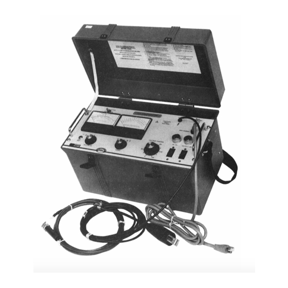
Megger ATEC 210415 Series Manual (82 pages)
15 kV Megohmmeter Test Set
Brand:
Megger
| Category:
Measuring Instruments
| Size: 3 MB
Table of Contents
Table of Contents
4
1 Introduction
8
Figure 1: 15 Kv Megohmmeter Test Set, Catalog No. 210415
9
2 Safety Precautions
10
3 Receiving Instructions
12
4 Specifications
14
5 Description
20
Figure 2: Schematic Diagram of the 15 Kv Megohmmeter
23
6 Control & Connector Identification
24
Figure 3A: View of the 15 Kv Megohmmeter Test Set
24
Figure 3B: View of the 15 Kv Megohmmeter Test Set
25
7 Setting up
26
Preparation
26
Selection of Location
26
Clearances
28
Figure 4: Testing in a Substation
30
Figure 5: Testing Parking Lot Lighting
31
Figure 6: Testing Transformer Terminals
32
Figure 7: DC Motor Test Setup
33
Figure 8: Generator Test Setup
33
8 Operation
34
Test Procedure
34
Breakdown of Test Item
35
Normal Shutdown Procedure
36
Interrupting a Test
36
9 Operation Notes
38
Line Supply
38
Meter Range Settings During Transit
38
Megohm Readings
38
Correction for Internal Leakage
40
Stabilizing Switch
40
Use of Guard (See also Section 10)
41
Voltage Control Scale
42
Use of Regulation Curve
42
Step Voltage Testing
42
Fault Locating (Breakdown Testing)
43
External Current Meter
44
Figure 9: Regulation Curves with Stabilizer "OUT", 120V Supply
44
Figure 10: Typical Guard Connection to Cable Pothead
45
Figure 11: Guard Connection for a Typical Cable Test
45
Figure 12: Typical Guard Connection for an Oil Circuit Breaker
46
Figure 13: Typical Guard Connection for Transformer Test
46
10 Application Notes
48
Theory of Insulation Testing
48
Applying the Test Set
49
Measuring an Ungrounded Test Item
50
Figure 14: Two-Winding Transformer in Three-Terminal Form
51
Generalized Combined 2 and 3 Terminal Measurement
52
11 Routine Maintenance
54
Introduction
54
Inspection and Maintenance Procedure
54
12 Troubleshooting and Repair
58
General
58
Case Repairs
59
Repairs to Components of Chassis and Panel
59
Changing Line Voltage Tap (-47 Models Only)
60
Replacement of Output Cable W101
60
Replacement of Power Cord W1
61
Replacement of Meters or Meter Amplifier Board
62
Replacement of Megohmmeter Range Circuit
62
Replacement of Voltmeter Range Circuit
63
Replacement of Stabilizing Switch S1
63
Replacement of Circuit Breakers
63
Replacement of Voltage Control Autotransformer T1
64
Replacement of the K2 Assembly
64
Replacement of Chassis-Mounted Assemblies
65
Replacement of Circuit Card U2
65
Calibration of Voltmeter
65
Calibration of Megohmmeter
66
Adjustment of R1 in Stabilization Network
68
Trouble Location
70
Figure 15A: Interior View
73
Figure 15B: Interior View
73
Figure 16: Connections for Calibration of Voltmeter
74
Figure 17: Connections for Calibration of the Megohmmeter
74
13 Performance Check
76
14 Parts List
78
15 Warranty and Repairs
80
Warranty
80
Repairs
80
Advertisement
Advertisement
Related Products
Megger AVO210
Megger AVO300 Series
Megger AVO310
Megger AVO 830
Megger AVO 835
Megger ADX15A
Megger AV 835
Megger AVO 850
Megger AVO 840
Megger 1006-603
Megger Categories
Test Equipment
Measuring Instruments
Multimeter
Security Sensors
Portable Generator
More Megger Manuals
Login
Sign In
OR
Sign in with Facebook
Sign in with Google
Upload manual
Upload from disk
Upload from URL