
Related Manuals for Bacharach Neutronics 7100P


Summary of Contents for Bacharach Neutronics 7100P
- Page 1 MODEL 7100P PORT ABLE OXYGEN ANAL YZER - TRACE RANGE OPERATIONS MANUAL REVISION B (MNA0010) October 2014 Euro Version #C7-01-7100-01-0 North American Version #C7-01-7100-01-1...
- Page 2 Introduction Thank you for purchasing the Model 7100P Portable analyzer for PPM range oxygen measurement. The Model 7100P Portable analyzer is a user friendly, microprocessor controlled, oxygen measuring instrument. It has many features to offer the user which will be described in this manual.
-
Page 3: Table Of Contents
Table of Contents ……………………………………………………………....………. 2 Introduction ……………………………....…………………………..….. 4 For Your Safety Specifications ……………………………………………….………....…………… 5 ……………………………………………..…..6 Warranty and Intended Use Chapter 1 Principles of Operation ……………………………………..………..7 1.1 General …………………………………………...…..... 8 1.2 Features ………………………...….. 9 1.3 System Components ……………………………….... 14 1.4 System Configuration Chapter 2 Commissioning the Model 7100... -
Page 4: For Your Safety
For Your Safety: PLEASE • READ THIS MANUAL IN ITS ENTIRETY BEFORE ATTEMPTING INSTALLATION OR OPERATION! Attempting to operate the Model 7100P Portable analyzer without fully understanding its features and functions may result in unsafe conditions. • Always use protective eye wear and observe proper safety procedures when working with pressurized gases. -
Page 5: Specifications
Figure 1 Model 7100 Specifications January 2001, Rev. 1 Sensor Type: Mini-Zirconia Oxygen Sensor with Integral Heater. Measurement 0-10ppm /0-100ppm / 0-2000ppm oxygen. May be set to auto range or to a fixed range. Display: 0.75" LED digital display. Resolution: 0-9.9ppm : X.X, otherwise XX Color Coded LEDs for system status: Alarms 1 &... - Page 6 Neutronics Inc. Warranty Statement Neutronics Inc. warrants to the original purchaser, that the Model 7100P Portable analyzer to be free of defects in material and workmanship for a period of one (1) year from the date of shipment from Neutronics Inc.
-
Page 7: Chapter 1 Principles Of Operation
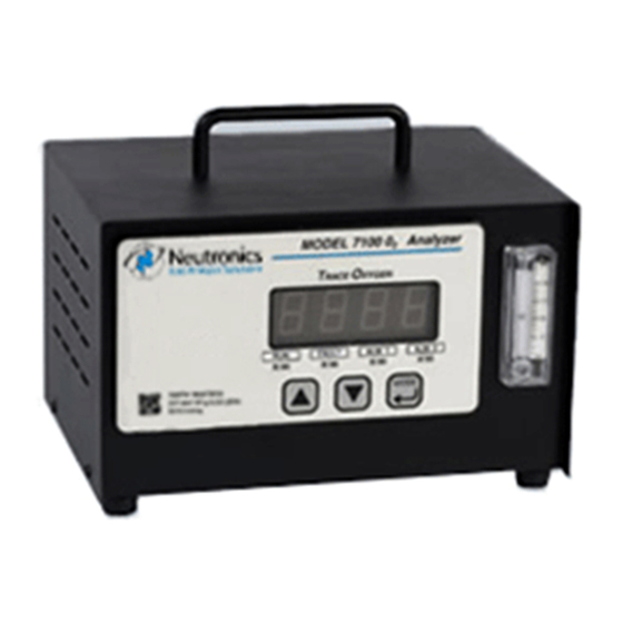
CHAPTER 1 Principles of Operation 1.1 General The Model 7100P Portable analyzer by Neutronics Inc. offers a cost effective solution in a small package for oxygen measurement and control applications. The Model 7100P Portable analyzer is a microprocessor based instrument FAULT ALM 1 ALM 2... -
Page 8: 1.2 Features
1.2 Features: The Model 7100P is designed to be portable for convenient use in the field. It requires connection to VAC power. There are two models available to meet power requirements of North America and for Europe. Provided with the 7100P is a Stainless Steel Sample tube with 1/8 inch Swagelok connection. - Page 9 The basic components of the model 7100P Portable analyzer are shown below in Figure 4: Figure 4 Flow Meter Bypass Valve Control Module fitting Sample Inlet Port Pump Internal Assembly of the Analyzer Control Module MNA0010, Revision B October 2014...
- Page 10 Figure 4 cont… Power Switch Flowmeter Power Socket Power Supply for Pump Fuse Ground 1.3.1 Main Board The microprocessor-based main board controls the operation of the Model 7100P Portable analyzer. The main board receives the sensor signal, amplifies it, and provides the control and display functions of the analyzer.
- Page 11 Control Panel: 1.3.5 The Control Panel serves as the main user interface. The Control Panel features the keypad (ramp-up, ramp-down, and mode keys) and the status LEDs The control panel is designed to be splash and water resistant. At the four corners of the panel are the #8-32 mounting studs which allow flush mounting of the instrument to a control or equipment panel.
- Page 12 Figure 7: Sensor Cell Block Cell Block: 1.3.7 This assembly (for local sensor mounting version) serves as both the receptacle for the sensor as well as the delivery system for the gas sample entering the analyzer. Gas is directed from the sample input port (1/8 inch Female NPT) through a flow restrictor to the face of the oxygen sensor.
-
Page 13: System Configuration
1.3.11 Sample Flowmeter: The sample flowmeter indicates the flow through the sensor. Flow should be indicated as 1 SCFH on the flowmeter. Figure 11 Sample flow meter 1.3.12 Pump Power Supply : In addition to the power supply located within the controller, a second power supply is mounted within the 7100P chassis. - Page 14 Figure 13 Mains Power North American Input Version Pump Power Pump Supply 4-20 mA Output RS 232 COM Line Analog Voltage Output Controller Main Sensor / Power Board Control Supply Board Display Board Controller Control Panel MNA0010, Revision B October 2014...
- Page 15 SYSTEM CONFIGURATION Figure 14 Mains Power Input Euro version Pump Power Pump Supply 4-20 mA Output RS 232 COM Line Analog Voltage Output Controller Main Sensor / Power Board Control Supply Board Display Board Controller Control Panel MNA0010, Revision B October 2014...
-
Page 16: Chapter 2 Commissioning The Model 7100
CHAPTER 2 Commissioning the Model 7100P Installation Figure 15 2.1.1 STEP 1 MAKE CONNECTIONS: MNA0010, Revision B October 2014... -
Page 17: Solder Reflow
The Model 7100P Portable analyzer is designed to be portable and used on location for various applications. It is designed for measuring oxygen in pure gases such as nitrogen, argon, helium,… It will not work in aggressive environments such as acid vapors, solvent vapors, or reactant gas environments found in semiconductor wafer manufacture. - Page 18 Metal, ceramic, wire annealing: In general, these processes use very clean ❑ atmospheres. However, there may be the need to filter excess particulates from the sample gas that could block sample tubes or sampling components. An internal sintered metal filter is mounted within the 7100p to catch particulates from damaging the sensor.
-
Page 19: High Purity Welding
CAUTION: The Model 7100P Portable analyzer features a heated mini-Zirconia sensor. Do not attempt to access the sensor or sensor control board until power has been removed from the unit and you have allowed sufficient time for the heater to cool down, about 5 minutes. - Page 20 control the pressure of the shield gas within the tubing to be welded. This is because you can control the shape of the weld bead as it is formed during the welding process. It is usually beneficial to force the bead to shape towards the outside diameter of the weld seam.
- Page 21 forces the purge gas to enter a confined area around the seam to be welded. Dams are available for various size tubes and feature quick connect fittings for easy coupling to the shield gas source. To position the dam around the seam, a chain or rope is connected at either end of the dam, and the assembly is pulled through the tube until in place.
- Page 22 2.1.2.2 Electrical Connections: When Using the 7100P as a monitor only, you need only connect the power input cord into the power socket and turn the unit on [after a 5 second purge]. It is possible to record the data via the RS-232 serial port, 4-20 mA analog output, or the analog voltage output.
- Page 23 Neutronics Inc. MNA0010, Revision B October 2014...
-
Page 24: Start-Up
Start-up 2.2.1 Last Check Before Power Up: Check List ? ….. Are you using the analyzer in an area where there are no flammable vapors? Avoid exposing the analyzer to rain, dripping water, or hose down? Installed the power cord and optional wiring? ... -
Page 25: Calibration
When the instrument is connected to power and turned on, the Model 7100P Portable analyzer will go into a self test mode. The digital display will show “8888” and the decimal point will scroll. The LEDs will flash. After approximately 8 seconds, the analyzer will display the software version number and then it will enable the warm-up of the instrument. - Page 26 value. Adjust the digital display to read the correct concentration of oxygen by pressing the UP or Down arrows as required. Press the “MODE” button again to scroll past the “ALM1” , “ALM2”, and Fault Modes as indicated on the display. MODEL 7100 O Analyzer Figure 26...
-
Page 27: Return To Run
MODEL 7100 O Analyzer The alarms will become RACE XYGEN active approximately 120 seconds after exiting the calibration mode. FAULT ALM 1 ALM 2 Mini-Z MODE IRCONIA ENSOR FIGURE 27 SET ALARM MODE: A look at the Display Panel 2.2.5 STEP 6 Return to RUN mode: After setting the alarms, press the MODE button to scroll past the FAULT (FLT) mode to... -
Page 28: Power Up
CHAPTER 3 Modes of Operation PURGE & FAULT POWER UP CONFIGURE SYSTEM SELF TEST & WARM UP FAULT STATUS RUN MODE Alarms to Normal Figure 28 after timeout SET / VIEW ALARM 2 FREEZE ALARMS ALARM(S) ENABLED SET / VIEW ALARM 1 CAL MODE After the unit has been calibrated on a known gas source, it can be used in normal operation. -
Page 29: Calibration
A description of each mode: NTRON MODEL 7100 O Analyzer RACE XYGEN Normal RUN mode is indicated by a green LED. The instrument is measuring the concentration of the sample FAULT ALM 1 ALM 2 gas and updating the display Mini-Zirconia MODE and outputs accordingly. - Page 30 It takes approximately 5 seconds to sweep the sensor out when zero gas is swept through the analyzer. Then you can apply power to the analyzer. Exposure to air does not affect the life of the sensor. 3.2.1 Two Point Calibration Design : The model 7100P Portable analyzer has been factory calibrated using two calibration gases and verified at several other points within the range of the unit.
- Page 31 The Model 7100P Portable analyzer will resume normal RUN mode operation when the UP, DOWN, or MODE buttons have not be pressed within a 120 seconds period. For Two Point Calibration: After the second calibration gas (500 to 1000 ppm O2) has been applied to the analyzer and the display has stabilized, press the “MODE”...
- Page 32 SET OR VIEW ALARMS Alarms 1 & 2 are indicated by a red LED plus dry relay contacts. The alarms will be indicated when the oxygen concentration has violated the threshold criteria of the respective alarm setpoint. The Alarm status will be cleared when the alarm condition has ceased.
- Page 33 MODEL 7100 O Analyzer RACE XYGEN FAULT ALM 1 ALM 2 Mini-Zirconia MODE Sensor Setting the alarm points: After the unit has been calibrated on a known gas source, it is desirable to set the alarm points. Scroll through the menu by pressing the “MODE” button until “ALM1” is displayed. Adjust the up and down buttons accordingly.
-
Page 34: Alarm Active Mode
NTRON MODEL 7100 O Analyzer FL – Diagnostic Fault display RACE XYGEN The FAULT mode will be indicated when the analyzer has detected a possible problem with calibration, hardware, or software. In addition to the yellow LED, a FAULT ALM 1 ALM 2 relay contact (SPST- N/O) is provided. -
Page 35: Analog Outputs
CHAPTER 4 Analog Outputs The Model 7100P Portable analyzer provides three analog outputs: • DC Voltage for oxygen concentration: 0-1, 0-5, or 0-10 VDC (jumper selectable) • DC Current for oxygen concentration: 4-20 mA • DC Voltage for range Identification: 0-10 ppm …………….………. -
Page 36: Chapter 5 Alarm Outputs
CHAPTER 5 Optional Alarm Outputs The Model 7100P Portable analyzer can be purchased with three optional alarms outputs: 1. Alarm 1, settable for concentration of oxygen (1 Form C relay contacts SPDT can be configured for fail safe or non-fail safe / ascending or descending trip. See section 3.3) 2. - Page 37 CHAPTER 6 Service Port: Serial Communications Interface The model 7100P Portable analyzer features a service port which is accessible for monitoring the analyzer output and for determining the active fault codes. The service port has been designed for communication with a PC based computer (such as a Portable analyzer notebook computer) over a standard RS-232 serial interface.
- Page 38 There are several timed update formats of the ASCII dump available: • 0 none Timed Outputs disabled • 1 Human Output tailored to reading by human • 2 Machine, no checksum Output tailored to use by a host computer • 3 Machine w/ Checksum Output includes a trailing Checksum to insure data integrity •...
- Page 39 Connection to the Service Port can be made at the terminal blocks on the rear of the analyzer chassis. The terminal blocks are removable for easy installation of the wires. Be certain to match the terminal pins against the terminal ID label on the top of the analyzer chassis. Access to the Serial Service Port may make through a terminal emulator program such as HyperTerminal available in Windows 95/98:.
- Page 40 Notes: If serial communications has not been established with model 7100P Portable analyzer, make certain that the PC SERIAL COM port is functional. This can be accomplished by jumping pins 2&3 on the RS 232 cable leading to the PC. To accomplish this test, disconnect the RS 232 cable from the model 7100P Portable analyzer port and insert a jumper between pins 2&3 on the cable connector or directly at the PC serial COM port.
-
Page 41: Maintenance
CHAPTER 7 Maintenance Maintenance for the Model 7100P Portable analyzer is very simple. Apart from the normal maintenance for any instrument such as cleaning the chassis & wiping the display, the Model 7100P Portable analyzer does not require any major servicing. Periodic calibration of the sensor on known gas should be performed on a regular basis (see section problems Recommended Frequency →... -
Page 42: Trouble Shooting
CHAPTER 8 Trouble-Shooting In some cases problems can be easily diagnosed and corrected. In other cases problems may require the user to return the analyzer to the factory for repair. Contact the customer service department identified at the front of this manual with any questions or when uncertain. - Page 43 Problem 2: Display reads too low. Cause: Improper calibration or sensor is failing. Solution: Recalibrate and/or install a new sensor as required. Problem 3: Erratic or intermittent display. Cause: If line power has been temporarily interrupted, the analyzer will restart itself. Solution: Avoid using the 7100P during electrical storms or when the power may be interrupted (during plant maintenance for example).
-
Page 44: Appendix A Spare Parts Listing
Appendix Contents: Spare Parts Listing MSD Data Service Port: Changing the Factory Settings Additional Drawings A: Spare Parts Listing Minor Spare Parts: VAC Fuses for VAC Power Supplies Operations Manual Replacement filter elements Sample Tube Power Cable Rubber feet Major Spare Parts: Oxygen Sensor Board VAC Power supplies Optional Relay Board... - Page 45 B: Material Safety Data (MSD) ... use as guide only, contact Neutronics Inc. for more information. Product Identification: Oxygen sensor, Solid State Type, Model ZrO2 Furnished by Neutronics Inc. Inc., 456 Creamery Way, SLC, Utah 19341 T: (801)972-2455 Hazardous Ingredients of Solution: none Health Hazard: none...
- Page 46 Service Port – Changing the factory settings The model 7100P Portable analyzer features the ability to manually alter the factory setting for serial output format, range selection, alarm relay configuration, analog output, and diagnostics. Changing the factory defaults may be accomplished through four methods: •...
- Page 47 6. Remove the screws/lockwashers holding the rear chassis of the control module on.. Set these aside for re-assembly. Slide the control module chassis off. 7. Turn the control module upside down so that the bottom of the main board is face up. 8.
- Page 48 TABLE C3: ANALOG VDC out jumpers JP4 / JP5 Jumpers Function Vout= 0-1 volt Vout= 0-5 volt Power Supply Board Relay Board Chassis Main Board Display Control Board Panel Vout= 0-10 volt Figure C.2: Accessing the Hardware Jumpers To change the factory settings by accessing the Level 1 software at the FRONT PANEL KEYPAD: In level 1 software (via the front keypad), you can change: •...
- Page 49 Table C3: Operational Table Range Name Measured Range Display Analog Range Range Voltage Output 0…10PPM Auto Range 0-10 ppm 3.13 Volts 3.75 0… 100 PPM 10-100 ppm 4.38 0 …1000 PPM 100-1000 ppm XXX. 0 …..2000 PPM 0-2000 ppm XXXX. 0…10PPM Fixed Range: 10PPM 0-10PPM...
- Page 50 The instrument range may be selected by the hardware jumpers or by this software range setup. To use the software setup, you must remove all of the four hardware jumpers. In the any fixed range, if the measured concentration is outside of the selected range or outside of the display’s ability, the value will be shown in PPM oxygen, and the display will flash.
- Page 51 The first point should be an air cal. The second calibration point, “Zero Range Code” , should be carried out with a certified gas of a concentration of oxygen near or in the range of primary measurement (For example, 0% oxygen in nitrogen).
- Page 52 15 USER CONFIG 8: Display shows ‘8 0’ – Restore Factory Settings This mode allows the operator to restore the instrument to the factory set points. This includes all calibrations, alarms and baud rates. To perform this function, press the “UP” button until the display shows 8 88, then press the mode button.
- Page 53 Follow the on screen prompts to change or configure the instrument. NOTE: the F3 key is the exit button. You will be prompted to save or discard your changes upon exiting. From this first menu, you have access to general system information, the relay and analog output configurations, the instrument display range, and the operator lockouts etc.: *****>...
- Page 54 D: Additional Drawings … MNA0010, Revision B October 2014...
- Page 55 Figure E: Driving Motors with the optiuonal alarm relay contacts Model 7100 Alarm Contacts +12 vdc Customer relay VDC Common VAC HOT MOTOR VAC Neutral Quick Operation Instructions Model 7100P Portable analyzer START UP 1. Connect the sample gas inlet (1/8 inch NPT female port). Regulate to 1-3 PSIG. 2.
- Page 56 Total warm up time to reach best performance: approximately 5 minutes It takes about 3 minutes to warm up from a cold start. It takes about another 5 minutes to attain best signal stability. Always expose the sample inlet port to nitrogen (or inert gas flow) before power up of the 7100P Portable analyzer to purge resident oxygen from the sample lines and sensor.
- Page 57 1. Connect a calibrated standard gas to the sensor. Regulate the pressure to 1-3 psig. Enter “CAL” mode by pressing “MODE” . Press here to The display should enter the “CAL” indicate the mode concentration of the Press the Ramp Up calibration gas before &...
- Page 58 Understanding the Digital Display The numeric display features large, super bright LEDs. There are NTRON MODEL 7100 O Analyzer two modes of display: When the analyzer is in the “out of normal RACE XYGEN operating range” measurement range, the display will flash bright to dim.
Need help?
Do you have a question about the Neutronics 7100P and is the answer not in the manual?
Questions and answers
Where can I get to buy in South Africa?