Table of Contents
Advertisement
Quick Links
Advertisement
Table of Contents

Summary of Contents for nVent Hoffman T Series
- Page 1 T15 Instruction Manual...
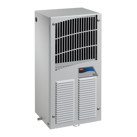
- Page 2 T-SERIES Air Conditioner t15 Model INSTRUCTION MANUAL Rev. I © 2019 nVent 89059119 P/N 10-1008-194...
-
Page 3: Table Of Contents
TABLE OF CONTENTS WARRANTY AND RETURN POLICY ..............................2 RECEIVING THE AIR CONDITIONER ............................... 3 HANDLING AND TESTING THE AIR CONDITIONER ........................3 INSTALLATION INSTRUCTIONS ..............................4 Design Data ........................................4 Dimensional Drawing ..................................... 4 Mounting Cutout Dimensions ..................................5 Components List ...................................... -
Page 4: Receiving The Air Conditioner
RECEIVING THE AIR CONDITIONER Inspect the air conditioner. Check for concealed damage that may have occurred during shipment. Look for dents, scratches, loose assemblies, evidence of oil, etc. Damage evident upon receipt should be noted on the freight bill. Damage should be brought to the attention of the delivering carrier -- NOT to nVent Equipment Protection -- within 15 days of delivery. -
Page 5: Installation Instructions
INSTALLATION INSTRUCTIONS 1. Inspect the air conditioner and verify correct functionality before mounting the air conditioner. See HANDLING AND TESTING THE AIR CONDITIONER on page 3. 2. Using the cutout dimensions shown page 5 in this manual, prepare the air “IN” and air “OUT” openings, and mounting bolt hole pattern for the enclosure. -
Page 6: Mounting Cutout Dimensions
MOUNTING CUTOUT DIMENSIONS 87981867 Externally Mounted Internally Mounted Cutout Instructions (As viewed from outside of enclosure) NOTE: Phantom lines represent air conditioner. COMPONENTS LIST Part Number Part Description 115V 230V Fan, Condenser 12-1012-01 12-1012-02 Fan, Evaporator 13-1015-01 13-1015-02 Capacitor, Compressor 52-6032-09 52-6032-10 Coil, Condenser... -
Page 7: Wire Diagrams
WIRE DIAGRAMS WITHOUT HEAT C-NET INDUSTRIAL LTD. | +44(0)121 544 8608 | INFO@CNET-IS.CO.UK | WWW.CNET-IS.CO.UK 89059119 - 6 -... -
Page 8: With Heat
WITH HEAT C-NET INDUSTRIAL LTD. | +44(0)121 544 8608 | INFO@CNET-IS.CO.UK | WWW.CNET-IS.CO.UK 89059119 - 7 -... -
Page 9: Schematics
SCHEMATICS With Heat Without Heat C-NET INDUSTRIAL LTD. | +44(0)121 544 8608 | INFO@CNET-IS.CO.UK | WWW.CNET-IS.CO.UK 89059119 - 8 -... -
Page 10: Temperature Control
TEMPERATURE CONTROL The electromechanical thermostat is factory preset to 75 F/23 C. To change the temperature setting, remove the nylon plug from the front face of the unit. Use a standard screwdriver to adjust thermostat. For cooler temperatures turn clockwise, for warmer temperatures turn counterclockwise. Setpoint differential is 6 F. UNITS WITH HEAT With a dial setting of 75 F, heat will turn on @ 70 F and turn off @ 75 F. -
Page 11: Maintenance
MAINTENANCE COMPRESSOR The compressor requires no maintenance. It is hermetically sealed, properly lubricated at the factory and should provide years of satisfactory operating service. Should the refrigerant charge be lost, recharging ports (access fittings) on the suction and discharge sides of the compressor are provided for recharging and/or checking suction and discharge pressures. -
Page 12: Condenser And Evaporator Air Movers
CONDENSER AND EVAPORATOR AIR MOVERS Fan motors require no maintenance. All bearings, shafts, etc. are lubricated during manufacturing for the life of the fan. CAUTION Operation of the air conditioner in areas containing airborne caustics or chemicals can rapidly deteriorate filters, condenser coils, blowers and motors, etc. -
Page 13: Trouble Shooting
TROUBLE SHOOTING BASIC AIR CONDITIONING TROUBLE SHOOTING CHECK LIST 1. Check manufacturer’s nameplate located on the unit for correct power supply . 2. Turn on power to the unit. The evaporator (Enclosure or “COLD” air) fan should come on. Is there airflow? YES, proceed to step 3. -
Page 14: Symptoms And Possible Causes
SYMPTOMS AND POSSIBLE CAUSES: SYMPTOM POSSIBLE CAUSE Clogged fins on coil(s) Dirty filter fans not running Unit won’t cool Compressor not running Compressor runs, but has bad valves Loss of refrigerant Low line voltage at start. Should be +/-10% rated voltage. Compressor motor stuck Compressor tries to start but won’t run Bad contactor... - Page 15 NOTES C-NET INDUSTRIAL LTD. | +44(0)121 544 8608 | INFO@CNET-IS.CO.UK | WWW.CNET-IS.CO.UK 89059119 - 14 -...
- Page 16 NOTES C-NET INDUSTRIAL LTD. | +44(0)121 544 8608 | INFO@CNET-IS.CO.UK | WWW.CNET-IS.CO.UK 89059119 - 15 -...
- Page 17 nVent 2100 Hoffman Way Anoka, MN 55303 USA +1.763.422.2211 +1.763.576.3200 nVent.com C-NET INDUSTRIAL LTD. | +44(0)121 544 8608 | INFO@CNET-IS.CO.UK | WWW.CNET-IS.CO.UK P/N 10-1008-194 Rev. I 89059119...
- Page 18 +44 (0)121 544 6808 info@cnet-is.co.uk C-NET Industrial Solutions Limited Suite 12, Sandwell Business Centre Oldbury Road Smethwick B66 1NN United Kingdom...


Need help?
Do you have a question about the T Series and is the answer not in the manual?
Questions and answers