Table of Contents
Advertisement
Quick Links
Advertisement
Table of Contents

Related Manuals for FLIR Tau Camera Link


Summary of Contents for FLIR Tau Camera Link
- Page 1 Tau Camera Link Module Operation and Modification Application Note FLIR Commercial Systems 70 Castilian Drive Goleta, CA 93117 Phone: +1.805.964.9797 www.flir.com Document Number: 102-PS242-100-02 Version: 100 Issue Date: October 2011 Rev100 October 2011 Page 1 of 16 102-PS242-100-02...
-
Page 2: Table Of Contents
Communication with other Frame Grabbers ................15 External Sync ..........................15 Table of Figures Figure 1: Tau Camera Link Module installed on a Tau 640 camera............. 4 Figure 2: BNC to RCA Adapter ........................5 Figure 3: Device Manager showing proper driver installation ..............6 Figure 4: FLIR Camera Controller GUI Status Tab –... -
Page 3: Document
Tau camera and converts it to Camera Link. It is also possible to make hardware modifications to this board to enable communication over Camera Link as well as access to external sync. The FLIR website will have the newest version of this document as well as offer access to many other supplemental resources: http://www.flir.com/cvs/cores/resources/... -
Page 4: Camera Link Operation
Link. In order to use a Camera Link Module for acquisition of data, you will need to first enable the CMOS XP Bus Output using the FLIR Camera Controller. This option is found in the FLIR Camera Controller GUI under Video => Digital Video. In the Camera Controller GUI, you can select either 8-bit or 14-bit digital output. -
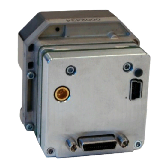
Page 5: Physical Connection
Camera Link Module Accessory 1. If you have an older version of the FLIR Camera Controller GUI loaded on your PC, you should first uninstall it using the Windows Uninstall utility via the Windows Control Panel before proceeding with this installation. -
Page 6: Software Connection
PC using a USB cable and the Camera Link Accessory Module. Please refer to the FLIR Camera Controller GUI User’s Guide for more details on functionality of the FLIR Camera Controller GUI and the Tau camera. -
Page 7: Figure 4: Flir Camera Controller Gui Status Tab - Not Connected
Camera Link Module Accessory Figure 4: FLIR Camera Controller GUI Status Tab – Not Connected → 3. Connect to the camera by selecting Tools Connection Figure 5: FLIR Camera Controller GUI Connection Window Part 1 Rev100 October 2011 Page 7 of 16... -
Page 8: Digital Data Via Camera Link
Next. If you only have one serial communication port on your computer, the button will say Finish. Figure 6: FLIR Camera Controller GUI Connection Window Part 2 5. Select the Com port seen in the Device Manager and click Finish. -
Page 9: Figure 8: Flir Camera Controller Gui - Digital Tab
This can be done on the Setup Tab by clicking the “Save Settings” button. 4. The digital data complies with Base Camera Link standards and will be compatible with most off- the-shelf Camera Link frame grabbers. FLIR has tested the ImperX FrameLink Express frame grabber (http://imperx.com/frame-grabbers/framelink-express) and the Matrox Solios Camera... -
Page 10: Figure 9: Imperx Framelink Express Software - Camera Parameters Window
JPG, TIF, and RAW) as well as standard AVI clips. Configuration requires selecting: “1 TAP, L->R” for the tap reconstruction, selecting the same bit depth that you chose in the FLIR Camera Controller GUI in step 2, and clicking “Learn” to discover the number of digital pixels available. -
Page 11: Troubleshooting The Flir Camera Controller Gui
2.6 Troubleshooting the FLIR Camera Controller GUI If the FLIR Camera Controller GUI does not link with the camera, you may see the popup shown below which indicates that the GUI has not been able to communicate with the camera. -
Page 12: Hardware Change
Camera Link Module Accessory This section describes an optional hardware modification for serial communications through the Camera Link connector and explains its use with an IMPERX FrameLink Express Frame Grabber. By default, the CL board uses USB to communicate with the Tau and is effectively a VPC module plus Camera Link digital data. -
Page 13: Communication With Camera Link Frame Grabber
57600. Note that the IMPERX FrameLink Express is not capable of communicated at baud rates exceeding 115200 and so the FLIR Tau option of 921600 is not available. This Terminal window will allow you to manually enter HEX commands. Refer to the Tau Software IDD for a list of available software commands. -
Page 14: Figure 16: Framelink Express - Terminal Window
Figure 16: FrameLink Express – Terminal Window It is also possible to create a Virtual COM port that can be used by the FLIR Camera Controller GUI. This is the preferred method because you will have full access to all camera controls. With the Camera Link card inserted and FLIR Camera Controller closed, run “FrameLink Express Virtual COM port”,... -
Page 15: Communication With Other Frame Grabbers
57600 or 921600 baud. Camera Link communications standards call for a differential serial connection and so the FLIR Camera Link Expansion Board includes a differential serial line driver to convert signals to RS-232 type signals for the Tau core. The following schematic shows connections on the FLIR Camera Link board and the line driver. -
Page 16: Figure 19: Ext Sync Header Connection
Camera Link Module Accessory The metal case will also require modification to allow the wire to pass out. A small hole can be drilled in the metal case to match the approximate location shown in the image of the camera assembly. Figure 19: Ext Sync Header Connection Figure 20: External Sync Location Rev100...
Need help?
Do you have a question about the Tau Camera Link and is the answer not in the manual?
Questions and answers