Table of Contents
Advertisement
FLIR
LEPTON® Engineering Datasheet
General Description
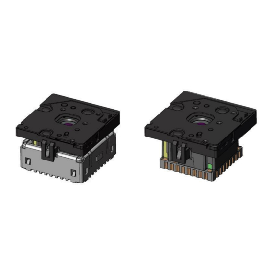
Lepton® is a complete long-wave infrared
(LWIR) camera module designed to interface
easily into native mobile-device interfaces and
other consumer electronics. It captures infrared
radiation input in its nominal response
wavelength band (from 8 to 14 microns) and
outputs a uniform thermal image with
1
radiometry
to provide temperature image with
measurements.
Lepton Features
•
Integral shutter configurations
•
Configurations with 25°, 50° and 57°
HFOV (f/1.1 silicon doublet)
•
LWIR sensor, wavelength 8 to 14 µm
•
Arrays with 80x60 and 160x120 active
pixels available
•
Thermal sensitivity <50 mK
•
Integrated digital thermal image
processing functions, including
automatic thermal environment
compensation, noise filters, non-
uniformity correction, and gain control
•
Radiometric accuracy
o High gain: ±5C @ 25°C
o Low gain ±10C @ 25°C
•
Radiometric Leptons
temperature measurement including
per pixel and frame radiometric output
(TLinear) and Spotmeter
•
Export compliant frame rate (< 9 Hz)
•
SPI video interface
•
Two-wire I2C serial control interface
1
Radiometric Leptons are 2.5 and 3.5.
The information contained herein does not contain technology as defined by the EAR, 15 CFR 772, is publicly available,
1
2
1
(35°C blackbody)
1
feature
and therefore, not subject to EAR. NSR (6/14/2018).
Information on this page is subject to change without notice.
Lepton Engineering Datasheet, Document Number: 500-0659-00-09 Rev: 203
•
Uses standard cell-phone-compatible
power supplies: 2.8 V to sensor, 1.2 V to
digital core, and flexible IO from 2.8 V
to 3.1 V
•
Fast time to image (< 1.2 sec)
•
Low operating power
o Nominally 160 mW
o 800mW typical during shutter
event (~1s)
o Low power mode 5 mW
•
RoHS compliant
•
32- pin socket interface to standard
Molex or similar side-contact connector
Applications
•
Mobile phones
•
Gesture recognition
•
Building automation
•
Thermal imaging
•
Night vision
2
All specifications subject to change without notice
Advertisement
Table of Contents


Need help?
Do you have a question about the Lepton 1.6 and is the answer not in the manual?
Questions and answers