Table of Contents

Related Manuals for ALLEN & HEATH iLive Series


Summary of Contents for ALLEN & HEATH iLive Series
- Page 1 iLive Reference Guide Part 2 – Firmware Firmware Version 1.7 This guide describes the iLive system operating firmware and how to use its feature set. For information on connecting iLive hardware please refer to Part 1. Publication AP6526-2...
-
Page 2: Contacts And Further Information
Welcome Thank you for investing in the Allen & Heath iLive digital mixing system. To get the most from your iLive we recommend you read the whole of this guide. To get started quickly refer to the Getting Started guides that come with the iLive Surface and MixRack, and then to this guide for further reference. This guide describes the iLive system operating firmware and how to use its feature set. -
Page 3: Table Of Contents
Table of Contents Contacts and further information................2 Introduction to iLive firmware..................5 Modular iLive controls and functions................. 6 Fixed format iLive controls and functions..............9 The Status screen ...................... 8 Surface basics – The TouchScreen................. 10 Fader control strip ..................13 The SEL key .................... - Page 4 System Firmware ..................... 84 Updating Firmware..................86 Network setup and connections................88 Reset network settings ................89 Multicast settings..................90 Connecting a laptop running iLive Editor ..............91 Connecting an iPhone running iLive Tweak............92 Dual MixRack configuration – Fixed format using ACE........... 96 Troubleshooting .......................
-
Page 5: Introduction To Ilive Firmware
Introduction to iLive Firmware iLive and the iLive-T Series provide a modular system for live sound mixing. Allowing distributed control and audio over CAT5 cable, iLive is well suited to demanding live sound applications such as FOH/Monitor mixing, live recording and multi-function installed venue sound. It is uniquely flexible with choice of components, a fully configurable bus architecture and assignable user interface for easy configuration to match each application. -
Page 6: Modular Ilive Controls And Functions
Modular iLive controls and functions USB ports Audio module options Two USB ports available 4x card slots A, B, C and D to fit optional audio input and output in addition to the two modules. Any input socket can be routed to any iLive channel using under the armrest at the PREAMP screen. -
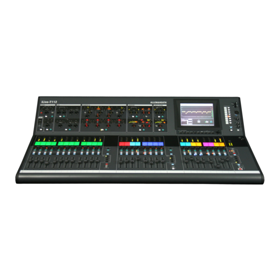
Page 7: Fixed Format Ilive Controls And Functions
Fixed format iLive controls and functions Channel Processing Strip Analogue style control TouchScreen For status display, section with dedicated rotary controls, switches and system setup and memory management. meters for the channel or mix preamp, HPF, gate, PEQ, To see an alternative graphical view of compressor and limiter/de-esser. -
Page 8: The Status Screen
The Status screen The TouchScreen ‘Status’ screen is displayed when the fader strip keys and the keys below the screen are all off. It is the default view when nothing is selected. It provides display of a real time clock, system status and access to the user assignable custom meters and the RTA display. - Page 9 Clock Displays the TouchScreen CPU real time clock. The time may be changed from the UTILITY / Configuration / Date Time page. Current User The current User name is displayed here. To log in as a different user go to the UTILITY / Change User page.
-
Page 10: Surface Basics - The Touchscreen
Surface basics – The TouchScreen The TouchScreen provides a graphical display of the parameters and assignments, allows configuration of the system, and management of the memories and data. Unlike many other digital consoles it is not essential to the live mixing operation. iLive avoids fiddly screen and menu based mixing by providing a large analogue style channel processing interface with dedicated rotary controls, switches and indicators. - Page 11 All screen keys turned off – STATUS With all the screen keys and strip keys turned off the TouchScreen displays the Status page. This shows system status including firmware, temperature, audio system lock and digital audio network status. A red cross means a problem is detected.
- Page 12 Access the FX rack. Provides 8 virtual ‘rack positions’ for loading your choice of processing from a library of effects devices including reverbs, delays, modulators and more. A Front Panel view presents a familiar control interface for parameter data entry. A Rear Panel view lets you ‘patch’...
-
Page 13: Fader Control Strip
Surface basics - Fader control strip The Fader Control Strip is the primary user interface for mixing with iLive. It provides a familiar analogue console layout and is arranged in banks across the surface. The smallest iLive surfaces have two banks of faders, the larger models have three. - Page 14 Rotary encoder This control lights up when it has a function assigned. It is used as a Send level, PAN or image control, or access to Preamp Gain depending on the type of mix currently selected with the key and whether it is a fader or rotary mix or an alternate function set up in Alt View.
- Page 15 Fader The fader is motorised and automatically changes position to reflect the current mix setting when you select different fader layers or change the mix using the keys. They also change to show the mix master GEQ (graphic EQ) settings when in GEQ FADER FLIP mode. Layers Change fader function BANK...
-
Page 16: The Sel Key
Surface basics – The The primary function of the fader control strip keys is to access the signal processing and routing for the channels, FX, mix or DCA masters. These keys are also used while in system setup mode to configure the strip functions, names and colours. -
Page 17: Input Channel Parameters
Input Channel Parameters Using a key to access Input socket patch Insert bypass Limiter / De-esser Insert Preamp Gate Compressor Name and Colour Delay CHANNEL PARAMETER CONTROLS PROCESSING VIEW ROUTING VIEW Mono Input CH fader, pan, mute Stereo Input Main mix assign FX return via Input Group assign Aux sends... -
Page 18: Mix Master Parameters
Mix Master Parameters Using a key to access Ext Input preamp Insert bypass Insert Limiter Ext Input Preamp Compressor Name and Colour Delay CHANNEL PARAMETER CONTROLS PROCESSING VIEW ROUTING VIEW Master fader, pan, mute Main mix assign CH Aux sends Mono, stereo CH pre/post... -
Page 19: Short Fx Return Parameters
Short FX Return Parameters Using a key to access CHANNEL PARAMETER CONTROLS PROCESSING VIEW ROUTING VIEW CH fader, pan, mute FX short return Main mix assign Group assign Aux sends FX sends DCA assign The iLive ‘RackExtra’ DSP mix engine provides a virtual rack to load up to 8 effects devices such as reverbs, delays and modulators. -
Page 20: Dca Settings
DCA Settings Using a key to access Assign from: Input channels FX return channels Group masters Aux masters Main mix masters Matrix masters DCA master With all TouchScreen keys off press a DCA master strip key to open its assignment view. Touch the screen buttons to toggle the assignments on or off. -
Page 21: The Mix Key
Surface basics – The MIX key The primary function of the fader control strip keys is to access the routing and levels for the different mixes, and to assign the DCAs. This is fundamental to mixing with iLive giving you quick access with full fader or rotary encoder control of every mix. -
Page 22: The Master Mix Key - Sends Feeding One Mix
Using the Master MIX key View all sends feeding one mix. Press on the mix master strip. View the current settings on the Select mix channel strip LCDs and faders/rotaries. To assign individual channels to the mix, hold down the ASSIGN key and then press channel keys to toggle them on or off. -
Page 23: The Channel Mix Key - Sends From One Channel
Using the Channel MIX key - View all sends from one channel. Press on an input channel strip. View the current sends and Select mix assignments from that channel on the master strip LCDs and faders/rotaries. To assign to individual groups or sends, hold down the ASSIGN key and then press master keys to toggle them on or off. -
Page 24: Channel And Mix Processing
Channel and Mix processing iLive provides plenty of signal processing for its input channels, effects returns, mix masters and up to 8 internal stereo FX devices. This replaces the large racks of outboard equipment that typically accompany the traditional analogue mixing system. iLive has a huge amount of DSP power to make its processing available to all channels at all times. - Page 25 PREAMP controls This section controls the Gain, Pad and 48V phantom power of the analogue mic preamp (head amp) at the input socket and before the A to D (analogue to digital) converter. These settings are not part of the channel processing as the preamp can be assigned to any one or more of the DSP channels.
- Page 26 EXT. INPUT (Mix only) You can patch a source as a mix master External Input. To open up the view touch the EXT INPUT section in the top level ‘thumbnails’ view for the master. MixRack Surface Port A Port B Rack FX Surface Talkback Ext Input patch bay...
- Page 27 GATE (Channel only) The noise gate provides a full set of controls and signal metering as you would find on a top grade outboard processor. The side chain filter may be switched in or out and self keyed or keyed from another input (within an associated range of 8 DSP channels).
- Page 28 (Channel, FX return and Mix) The equaliser is 4-band fully parametric with cut/boost, swept frequency and width controls per band. The HF and LF bands may be switched as shelving, bell or pass type filters. The WIDTH control turns off if the band is set as shelving. GAIN turns off if the band is set as a pass type.
- Page 29 (Mix only) A third octave graphic equaliser is provided for every mix output. This gives you up to 32 GEQs depending many mixes have configured. The GEQ has 25 bands from 63Hz to 16kHz. To access the GEQ touch the GEQ tab or the box in the mix master ALL screen.
- Page 30 COMPRESSOR (Channel and Mix) The compressor provides a full set of traditional controls and signal metering as you would find on a top grade outboard processor. A side chain filter which can be self keyed or keyed from one of 7 adjacent channels may be switched in or out.
- Page 31 LIMITER / DE-ESSER (Limiter on Channel and Mix, De-Esser on Channel only) This is the last of three dynamics processors available on every input channel. It can be used either as a ‘brick wall’ limiter to stop the threshold level being exceeded or as a de-esser to filter out the sibilance of a vocal source.
-
Page 32: Introducing The Fx
Introducing the FX The iDR-64 ‘RackExtra’ DSP mix engine provides a virtual ‘FX rack’ which can be configured with up to 8 processors including reverbs, delays, modulators and more. It also features a host of new routing possibilities for patching FX inputs and outputs and configuring mix/return or inserted FX types. FX Rack A virtual rack with 8 ‘slots’... - Page 33 Back Panel view - Configure the FX routing FX configuration Apply the change Send to the FX (FX input) Return from the FX (FX output) Send/Return masters or Wet/Dry controls depending on configuration Touch the top right Back Panel button to open up the connections view. This emulates patching up a typical outboard effects rack.
- Page 34 Front Panel view – Work with the FX parameters Select rack slot Adjust parameters Highlight scroll through effects presets using encoder FX send and return master settings Library Opens the FX FX presets return PEQ and DFX windows Access FX parameters from the strips Press an FX send master Access FX strip...
- Page 35 Choose the FX – The FX preset library Touch the Library button to open up the library list. The presets are grouped into Factory, User and USB. Factory Default presets that cannot be overwritten, and can be used as the starting point for creating your own presets. User Edited settings may be named and stored here for future recall.
- Page 36 Reverbs - SMR Arena 1 Arena 2 Chamber Large Chamber Mid Chamber Small EMT + Echo EMT 250 EMT HF Vocal EMT Large EMT Live Hall 480 Hall 481 Live Hall 482 Live Hall Barfoot Spatial Modelling Reverberator. These provide high quality stereo reverb Hall Brass effects based around 4 complex spatial models - Classic, Hall, Room and EMT.
- Page 37 Modulation FX - ADT ADT 2Trk Vox ADT Choral Dly ADT Classic ADT EkoChorus The ADT DOUBLER is an automatic double tracking module for creating short echo/chorusing effects, classic double tracking and ‘slapback’ tape delay loops. It emulates the classic ADT effects that are popular in enhancing sources such as vocals and guitars in live sound mixing.
- Page 38 Modulation FX - MOO Phaser MOO Classic MOO Manual MOO Spatial A classic 12 stage emulation producing rich textured phasing with plenty of control. The user has control of number of stages, feed forward and feed back, and ‘zero’ depth manual mode – to manually sweep the Phaser using the offset control.
- Page 39 Hypabass Beware Infra Lost Fundamental A sub-harmonic synthesis unit classically used in the live sound environment to generate infra and sub bass spectrum from weaker bass programme. We initially emulated the American analog classic, but implementation in DSP gave us the ability to use more sophisticated techniques in the sub harmonic generator and filtering stages.
- Page 40 Gated Verb Gate Echo Gate RevPan Gate Short Gated Big Pan Gated Drum Big Gated Drums Sml Gated Kick Gated Rev Gated Snare Gated Vocal ‘Gated Verb’ hosts the classic 80’s emulation plus ‘panned’ and ‘powerbox’ gated reverb presets. The user interface gives instant access to lo-cut hi-cut decay spectrum filters and the gate envelope controls.
-
Page 41: Patching The Outputs
Patching the Outputs Press the OUTPUTS key below the TouchScreen to access the output routing patch bays. These virtual patch panels display the physical and digital audio network output sockets recognised by the system and let you route any signal to any output. Choose the signal to send to the socket: Tabs to select patch... - Page 42 Output Sources The user assigned name is displayed below the channel number. If a channel is not available a red cross appears. Note: If sockets have been assigned as INSERT Sends then they are not available to be assigned using the OUTPUTS page.
-
Page 43: Using Dca And Mute Groups
Using DCA (and MUTE) groups iLive provides 16 DCA groups. These behave in a similar way to conventional analogue console VCA groups. You may assign as many of these as you choose to the Surface strips. The DCA master fader does not physically move the assigned channel faders. -
Page 44: Channel Ganging
Channel Ganging Ganging lets you link selected processing and mix parameters between input channels or masters, for example the EQ, gate and compressor of a stereo keyboard, or the GEQ of the L and R main mix. iLive lets you create up to 8 gangs with up to 8 channels in each. Ganging does not include the input Preamp (Gain). -
Page 45: Using Copy / Paste / Reset Edit Keys
Using the COPY / PASTE /RESET edit keys iLive provides a quick and intuitive edit function to copy or reset settings between channels, processing blocks and mixes. This uses dedicated edit keys on the Surface rather than complex screen menus. Information iLive-144 Surface COPY / PASTE / RESET keys... - Page 46 COPY Hold down COPY then press the associated with the parameters you want to copy. This puts the parameters on to a ‘clipboard’ to be pasted later. Hold with: Channel or mix key – Copies all the processing associated with the channel. Note: The input PREAMP gain, pad and 48V settings are not copied.
-
Page 47: The Meters Screen
The METERS screen Press the METERS key below the TouchScreen to view pages of audio meters. You can configure and view up to 4 ‘User’ meter pages. The RTA frequency analysis display is available within this view. The User meters and RTA are also accessible on the Status page for convenience while mixing live. These meters views are in addition to the extensive physical metering provided on the iLive Surface. -
Page 48: Pafl Monitor System
PAFL monitor system iLive features a comprehensive engineer’s monitoring system with headphones and local monitor outputs available at the Surface, and headphones duplicated at the MixRack. The audio anywhere in the signal path can be listened to using these monitor outputs, and checked on the dedicated PAFL meters. Dedicated Surface and TouchScreen controls and user preferences let you configure the monitor system the way you want to work. - Page 49 PFL/AFL mode keys Master keys to the right of the strips select the function of the PAFL keys to be PFL (pre-fade listen) or AFL (after-fade listen). Signals are monitored in mono or stereo depending on their configuration. AFL is pre-mute so you can check it before sending it, and ‘stereo in-place’ so you can check it after the pan and image controls.
- Page 50 PAFL IN sockets This pair of balanced, line level XLR inputs on the rear of the modular iLive Surface lets you add an external signal to the PAFL mix. Two applications are: iLive Surface No ESA LOCAL MON OUT PAFL IN XLR CABLES LOCAL MONITOR iDR10...
- Page 51 TouchScreen PAFL functions Press the TouchScreen PAFL key to open a page of option settings for the PAFL monitoring system. Set these according to your preferred way of working. These settings are retained on power down. Ext IP Talk to PAFL Turns on or off the source assigned for external MixRack input talkback into the PAFL monitor.
-
Page 52: Engineer's Wedge / Iem Monitoring
Engineer’s Wedge / IEM monitoring The iLive is capable of being configured for dedicated monitor mixing. It can provide an engineer's dual Wedge/IEM facility for monitor mixing with combinations of stage wedge speakers and in-ear monitors. This lets you assign mono or stereo Wedge and/or IEM masters strips on the Surface. Mixes sent to the stage wedges can be monitored in just the engineer's Wedge output, and mixes sent to the in-ear systems can be checked using just the IEM output. -
Page 53: Talkback System
Talkback system iLive provides a fully featured engineer’s Talkback system. This uses dedicated Talk keys and is quick to assign to the outputs without the need to access screen menus. The Surface has a built-in Talkback microphone input which can link to the MixRack via the Port A digital audio network or an analogue connection (iLive only). - Page 54 Talkback setup and preferences TALK key action Select either momentary (push to talk) or latching (using a switched mic) operation. Go to the SURFACE SETUP / Preferences page. Set the Latching Talkback Talk Switch option. Talkback Source Choose the source for the Talkback system from the drop down menu in the MIXRACK SETUP / Talkback / Source page.
-
Page 55: Softkeys, Pl-Anet Remote Control, Midi
SoftKeys 8 SoftKeys to the right of the TouchScreen can be assigned to different functions to suit your application. For example, you could use them as MUTE GROUP masters, to recall Scene memories, quickly access processing or mix parameters of a certain channel or master, send a MIDI message and more. -
Page 56: Mixrack Setup
MIXRACK setup The MixRack is the heart of the system and features a 64 channel x 32 mix bus audio architecture that is fully configurable by the user. Once configured you can map the channels and masters to the Surface strips and layers in any combination. - Page 57 Top screen We refer to this as the ‘radar view’ as it provides an overview of the current system configuration. Use the menu buttons to access and change the configuration and other MixRack setup functions. Input Channels view Tabs let you access all 64 input channels and the FX short returns.
- Page 58 Mixer Config page This screen lets you change the mono/stereo configuration of the input channels, and the architecture of the mix buses. Note: Changing these settings reconfigures the DSP architecture and resets parameters. This can take up to 2 minutes to complete and is not intended for ‘on the fly’...
- Page 59 The Main Mix iLive features a choice of many different configurations of main mix from mono to 4way and with different types of image control. Note that due to the DSP architecture the buses are always allocated in pairs. Therefore a main mono ‘M’...
- Page 60 Mixer Preferences page This page lets you set the source to the input channel direct outputs globally, the global input channel preamp setting and PEQ frequency ranges. Global Direct Output Source Open the drop down menu and select the point in the channel signal path to feed the direct outputs.
- Page 61 Quick Input Source Setup page Allows for the quick changeover between Local physical input channel sources and digital audio network input channel sources for a range of inputs. This helps when setting up consoles and switching between single system operation and linked system operation, for example sharing mic inputs using a Port B digital mic split.
- Page 62 Signal Generator page Provides a comprehensive tone / noise generator which can be used for checking and setting up the system. The generator settings are restored on power up and stored in the system Show memories. They are not stored in Scene memories. Signal type Choose the generator signal source type:...
-
Page 63: Surface Setup
SURFACE setup Once the MixRack audio architecture has been configured using the MIXRACK SETUP screen, you can assign the channels, mix masters, DCA group masters and Wedge/IEM masters to the Surface strips. These are assigned to the strips within the fader banks and across the 4 layers, either one at a time or across a range of strips. - Page 64 Assigning the Surface Strips To assign a Single Strip Touch the Single Assignment button. Press key on the strip you want to assign. Use the drop down menu to select the Channel Type you wish to assign. Touch the Channel Number box PAFL PAFL to highlight it and use the screen encoder to scroll to the number required.
- Page 65 Assigning the Soft Keys 8 SoftKeys to the right of the TouchScreen can be assigned to different functions to suit your application. For example, you could use them as MUTE GROUP masters, to recall Scene memories, quickly access processing or mix parameters of a certain channel or master, send a MIDI message, Tap a Tempo and more.
- Page 66 Assigning PL Devices Allen & Heath PL remote control device may be plugged into either the MixRack or the Surface. These provide controls such as faders, rotary encoders, switches, indicators and logic GPIO which may be assigned by the user to suit the application. These controllers interface to the iLive using CAT5 cable via the RS485 based PL-Anet port.
- Page 67 The Surface ALT VIEW key The Surface fader strip LCDs normally display the channel names and the Channel Encoder acts as Pan. Hold down the ALT VIEW key to display alternative information such as channel or socket number, or dB value and access alternative encoder functions.
- Page 68 STRIP ROTARY FUNCTION the alternative encoder information that can be accessed is as follows but this setting also lets you choose which functions you want to access via the different levels of encoder function. You can define the function for the Main (default) operation, the Shifted operation and the Alternate operation of the Channel Strip Rotary control.
- Page 69 Setting the Surface Preferences You can set user preferences for how the iLive Surface functions. Go to the SURFACE SETUP / Preferences page. Link Fader Banks Set the Surface fader banks for independent or linked layer operation across all banks. This affects all fader banks. Display Parameter Values Display dB readings in the strip LCDs when the faders or encoders are moved.
-
Page 70: Name And Colour
Name and Colour Each Input channel, mix master and DCA master can have a 5 character name and one of 6 colours or no backlight applied to display on the Surface. The names appear on the strip LCDs and TouchScreen pages, and the colour affects the strip LCD backlights. -
Page 71: User Profiles
User Profiles iLive lets you set up and work with up to 8 'User Profiles'. You can set permissions and a password for each to restrict operator access to certain functions. The 'Admin' user (Administrator) has access to all functions and can set permissions and allocate passwords if required for the other users. -
Page 72: Library Memories
Library memories You can name, store and recall parameter settings as User libraries, or recall factory presets from the Library pane in each processing screen. Library types: Noise Gate Compressor Limiter/De-esser Full input channel processing Full mix channel processing FX emulations PL-Anet setup Touch the Library button to open up the library view. -
Page 73: Scene Memories
Scene memories iLive has 250 Scene memories. These are 'snapshots' of all or a selection of the live mixing parameters. They do not store the DSP bus configuration and user preferences. Before starting go to the SURFACE / Preferences screen and set the options to enable or disable the Scene Up/Down/Go keys, and turn on or off the Scene Editing Confirmation popup box. - Page 74 Using the Edit SCENE CONTENTS page Add selected items to a 'partial' scene Add selected parameters to a Scene You can store SCENE CONTENTS ‘partial’ Scenes. Select items from the list in the left hand Console window to add to the scene. Expand and collapse the tree Settings list using the + and –...
- Page 75 Scene parameters The diagram below lists the items that may be selected and added to the Scene memories. It also illustrates where the different parameters exist in the signal chain. The items are arranged as a tree view. You can expand and collapse tree items, and view it by Processing type or Channel number.
-
Page 76: Usb Scene Transfer
USB Scene Transfer Recalling a Show completely overwrites all system settings and the system configuration. This may not be ideal in a festival situation where several guest engineers arrive with their settings stored as Shows on their USB keys. You may not want important settings such as output processing and patching overwritten. The USB Scene transfer function lets you select Scenes or 'last settings', and transfer these to Scenes within the iLive. -
Page 77: Show Memories
Show memories You can archive your configuration as a Show memory. Show memories overwrite all the settings. These include all current parameters, system DSP and control configuration, all 250 Scenes and the user preferences. Shows are stored on the TouchScreen computer within the Surface and can be transferred between systems using a USB key. - Page 78 To archive your configuration go to the UTILITY / Factory default Template shows Configuration / Show Manager screen. Touch the Archive Show button. Type in a name using the onscreen keypad. Press Enter to archive the show. Archive existing settings This takes a few seconds to complete.
-
Page 79: Using Template Shows
Using TEMPLATE Shows The iLive has a fully configurable audio architecture and control layout and socket patching letting you customise the way you work. It would be a daunting task for the new user if we gave them a ‘blank canvas’... - Page 80 Fixed Format iLive - Factory Default Show Template Show = FOH-LRSub LRSub main mix CH1 - 60 = mono 4 mono, 2 stereo Groups Channels CH61/62, 63/64 = stereo 8 mono, 2 stereo Auxes 6 mono FX sends Bus configuration 6 Send/Return stereo FX 4 mono, 2 stereo Matrix 2 insertable stereo FX...
-
Page 81: Working With Usb Data
Working with USB data iLive can transfer its Show memories, libraries and log files between the onboard computer and an external PC or another iLive system via a USB memory key. You can also recall a show directly from the key without the need to copy it to the Surface first. -
Page 82: The Utility Screen
The UTILITY screen The UTILITY screen provides access to many setup, diagnostic and user preference functions. They are grouped into pages according to function type , for example, managing the memories and User Profiles, checking system status and diagnostics, setting up the network, or updating the operating firmware. Some of these functions may not be available if the current User Profile has functions deactivated. - Page 83 Configuration page Provides access to the memory management, time setup and MIDI settings. Date / Time View the current day and clock settings for the MixRack, Surface and TouchScreen. These are stored separately and may differ, for example if you are using a different MixRack with your Surface.
-
Page 84: System Firmware
Firmware page Lets you check the current system firmware versions and load in new firmware using a USB key. Firmware Versions Displays the current firmware versions for the TouchScreen, Surface and MixRack. They should all be the same version. If not the system would fail to connect and would prompt you to view and update its firmware during the boot up process. - Page 85 Update Firmware This page lets you load new firmware into the iLive. The process is very quick and easy. It automatically identifies firmware present on your USB key, checks if it is different to that currently loaded, identifies which of the TouchScreen, Surface and MixRack need updating, and prompts you to install it.
-
Page 86: Updating Firmware
Update firmware using the Surface USB port: Method 1 Step1 Download the firmware and read the Release Notes Visit http://www.ilive-digital.com/firmware/ Download the latest firmware and read the Release Notes. Save the zipped file to your Desktop or folder of your choice. Step2 Extract the Firmware folder Unzip the file. - Page 87 Update firmware using a PC running Editor software Method 2 Note: It is very important that the firmware update is not interrupted. Failure to complete the update may result in firmware corruption of the iLive which will require return to a service centre. To avoid problems ensure a reliable network connection.
-
Page 88: Network Setup And Connections
Network page Lets you view and change the system unit names and network settings. Network Connections This page displays the names, network addresses and connection status of the devices currently connected via Ethernet to the onboard TouchScreen computer. You can Use this screen if you are change which MixRack to connect to here. -
Page 89: Reset Network Settings
Unit Name Touch the box to open the touch keyboard and enter a unique name to identify each MixRack and Surface. Note: If you are using the Dual-Rack function to connect two MixRacks to one Surface then make sure each rack is identified with a unique name. -
Page 90: Multicast Settings
Multicast Setup If you are running Editor on a wireless laptop where signal strength is low or interference a problem you may notice the Surface meters freeze regularly too. This is because the MixRack sends meter data separately to both Editor and the Surface and waits for a response from each that it is received. -
Page 91: Connecting A Laptop Running Ilive Editor
Connecting a laptop running iLive Editor A laptop running Editor can control the iLive using a wired or wireless connection to any iLive NETWORK port. Wired - Plug a standard CAT5 network cable between the laptop Network port and any iLive NETWORK socket. Wireless - Plug a wireless router (wireless access point) into any iLive NETWORK socket using a CAT5 cable. -
Page 92: Connecting An Iphone Running Ilive Tweak
Connecting an iPhone running iLive Tweak iLive Tweak is an application for the Apple iPhone, iPad or iPod Touch. It can be downloaded from the iTunes store. Tweak requires firmware version V1.7 or greater. Ensure the latest firmware has been downloaded and installed on the iLive system from the Allen & Heath website. - Page 93 Download iLive Tweak iLive Tweak is compatible with the iPhone 3, 3G, 3GS and 4, iPad and iPod Touch. The application can be downloaded via the iTunes Store to a PC or MAC or directly onto the iPhone or iPad using the device App Store application. In both cases you will need your Apple ID and password.
- Page 94 Connect to the iLive To launch the iLive Tweak application, click on the icon on the iPhone home screen. Once launched you can select an iLive MixRack from the list. Make sure the iLive is powered on, the wireless router has been correctly configured and the iPhone Wifi is connected to the correct network.
- Page 95 Using iLive Tweak Once connected, a menu organised by channel type lets you select a channel to control. You can control level, mute, delay, PEQ and GEQ where appropriate by swiping left and right. To return to the menu use the ’Channel Selector’ button at the top of the screen.
-
Page 96: Dual Mixrack Configuration - Fixed Format Using Ace
Dual MixRack configuration – Fixed format using ACE Two MixRacks may be connected in Dual-Rack mode to expand the number of input channels from 64 to 128. The number of physical inputs available depends on which MixRacks are used. This does not expand the number of mix buses. -
Page 97: Troubleshooting
Troubleshooting Troubleshooting FAQ Also refer to the FAQ within the Help Manual available at the Surface TouchScreen and Editor software. Red Cross and yellow triangle errors A red cross displayed on the Status page when no screen or key is active warns you of an error detected in the system. If you are in a different screen a yellow triangle will appear in the bottom toolbar. -
Page 98: System Fails To Connect
System fails to connect If you get the CONNECTION FAILED screen when you boot the system up: Check that the cables connecting the MixRack and Surface are correctly plugged in and are not damaged. If you are using a two cable connection check that they are not crossed over or plugged into the wrong sockets. -
Page 99: Lost Connection
Lost connection If you get the CONNECTION LOST screen then the iLive has lost network connection after having successfully connected. Check that mains power is present at the MixRack if it is situated remote from the Surface. Check that the cables connecting the MixRack and Surface have not become disconnected or damaged. -
Page 100: Ilive Midi Specification
iLive MIDI Specification iLive supports MIDI control. Modular iLive provides MIDI IN, OUT and THRU connections at both the MixRack and Surface. Fixed Format iLive provides MIDI IN and OUT connections at both the MixRack and Surface. MIDI Link Function MIDI is tunnelled over the iLive TCP/IP network link. - Page 101 MIDI channel MIDI channel 1 to 16 = For Dual-Rack the Slave rack MIDI channel = Master rack MIDI channel + 1 Channel numbers (refer to table) FX Send 1 to 8 = FX Return 1 to 8 = DCA 1 to 16 = Input 1 to 64 = Mix 1 to 32 = Sysex Header...
- Page 102 Channel Assignment to Main Mix ON NRPN with parameter ID ON value = Select channel Parameter Set ON BN, 63, CH, BN, 62, 18, BN, 06, Channel Assignment to Main Mix OFF NRPN with parameter ID OFF value = Select channel Parameter Set OFF BN, 63, CH,...
- Page 103 Socket Preamp Pad Sysex message This turns Pad on or off for the preamp at a socket MixRack preamp socket ID A1 to J8 = Surface preamp socket ID A1 to D8 = To get Pad status from iLive Send… Sysex Header, 07, MP, Reply…...
- Page 104 Scene Recall Bank Program Change message To recall one of the 250 Scenes (2 banks) Also transmits this message when a Scene is recalled by TouchScreen or another method For Scene 1 to 128 Scene 1 to 128 = Select bank Recall Scene BN, 00, 00, For Scene 129 to 250...
-
Page 105: System Specification
Specification System Format Separate MixRack and Surface with control & audio over a single CAT5 ACE™ cable 64x32 RackExtra DSP mix engine located in MixRack Audio Network Port A Local audio to/from Surface - ACE™ up to 120m CAT5 (depending on cable)* Audio Network Port B Network option plug-in cards available - see website for details Con trol Network... -
Page 106: System Block Diagram
iLive Reference Guide – Firmware Part 2 - 106 AP6526-2 iss.4... - Page 107 iLive Reference Guide – Firmware Part 2 - 107 AP6526-2 iss.4...
Need help?
Do you have a question about the iLive Series and is the answer not in the manual?
Questions and answers