Sign In
Upload
Download
Table of Contents
Contents
Add to my manuals
Delete from my manuals
Share
URL of this page:
HTML Link:
Bookmark this page
Add
Manual will be automatically added to "My Manuals"
Print this page
×
Bookmark added
×
Added to my manuals
Manuals
Brands
Magnaflux Manuals
Industrial Equipment
D-2000 Series
Operation manual
Magnaflux D-2000 Series Operation Manual
Hide thumbs
Also See for D-2000 Series
:
Operation manual
(55 pages)
1
Table Of Contents
2
3
4
5
6
7
8
9
10
11
12
13
14
15
16
17
18
19
20
21
22
23
24
25
26
27
28
29
30
31
32
33
34
35
36
37
38
39
40
41
42
43
44
45
46
47
48
49
50
51
52
53
54
55
56
57
58
page
of
58
Go
/
58
Contents
Table of Contents
Troubleshooting
Bookmarks
Table of Contents
Table of Contents
General Safety Instructions
Section 1: Equipment Specifications
Scope of this Manual
Purpose of the Equipment
Equipment Characteristics
Equipment Specifications
Equipment Warranty
Section 2: Installation and Storage
General
Installation
Preparation for Storage or Shipment
Section 3: Operating Instructions
Operating Controls and Indicators
Daily Start up and Operation Checklist
Piece Part Setup
Magnetizing Procedures
Demagnetization
Shutdown
Emergency Shutdown
Section 4: Maintenance
General
Daily Operator Maintenance
Weekly Operator Maintenance
Monthly Operator Maintenance
Periodic Internal Maintenance
Operational Checkout Procedures
Initial Set-Up
Circular (Contact) and Longitudinal (Coil) Magnetization Check
Section 5: Troubleshooting
Troubleshooting Stack (Firing Board)
Troubleshooting Guide
Section 6 - Drawings & Spare Parts List
Section 7: Hood & Black Light Installation
Hood Installation
Black Light Installation
Advertisement
Quick Links
1
Equipment Specifications
2
Installation
3
Operating Controls and Indicators
4
Section 4: Maintenance
5
Troubleshooting Stack (Firing Board)
6
Troubleshooting Guide
7
Section 6 - Drawings & Spare Parts List
Download this manual
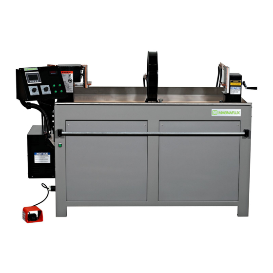
D-2000 SERIES
D-2000 Series
Revised March 2020
Page | 1-0
Table of
Contents
Previous
Page
Next
Page
1
2
3
4
5
Advertisement
Table of Contents
Troubleshooting
SECTION 5: TROUBLESHOOTING
41
Troubleshooting Guide
42
Need help?
Do you have a question about the D-2000 Series and is the answer not in the manual?
Ask a question
Questions and answers
Related Manuals for Magnaflux D-2000 Series
Industrial Electrical Magnaflux D-2000 Series Operation Manual
(55 pages)
Diagnostic Equipment Magnaflux D-2060 Series Installation Manual
Magnetic particle inspection machine (5 pages)
Industrial Equipment Magnaflux D-2100 Series Installation Manual
With mod 4.0 ac (5 pages)
Industrial Equipment Magnaflux D-2060 MOD 2.5 AC Operation Manual
(58 pages)
Industrial Equipment Magnaflux D-2100 MOD 4.0 Operation Manual
(58 pages)
Industrial Equipment Magnaflux D-2060 MOD 6AC Operation Manual
(58 pages)
Industrial Equipment Magnaflux D-2100 MOD 6AC Operation Manual
(58 pages)
Industrial Equipment Magnaflux A-2000 Series Operation Manual
(56 pages)
Industrial Equipment MAGNAFLUX Universal WE TOUCH with TCODE Operating Manual
Multi-directional magnetic wet bench (86 pages)
Industrial Equipment Magnaflux Y-6 Operating Manual
Ac / ac/dc magnetic yoke (44 pages)
Industrial Equipment Magnaflux Universal WE Installation Manual
(5 pages)
Industrial Equipment Magnaflux M-2060 Series Installation Manual
Magnetic particle inspection machine (3 pages)
Industrial Equipment Magnaflux ADH-2045 Series Installation Manual
(5 pages)
Industrial Equipment Magnaflux L-10 Operating Manual
(28 pages)
Industrial Equipment Magnaflux M-2030 Series Installation Manual
Magnetic particle inspection machine (3 pages)
Industrial Equipment Magnaflux A-2030 Series Installation Manual
Magnetic particle inspection machine (5 pages)
This manual is also suitable for:
D-2060
D-2100
D-2100xl4
D-2100xl5
D-2060l
D-2060xl
...
Show all
D-2060xl2
D-2060 mod 2.5 ac
D-2100 mod 4.0
D-2060 mod 6ac
D-2100 mod 6ac
Table of Contents
Print
Rename the bookmark
Delete bookmark?
Delete from my manuals?
Login
Sign In
OR
Sign in with Facebook
Sign in with Google
Upload manual
Upload from disk
Upload from URL


Need help?
Do you have a question about the D-2000 Series and is the answer not in the manual?
Questions and answers