
Subscribe to Our Youtube Channel
Related Manuals for SMC Networks LECSC Series


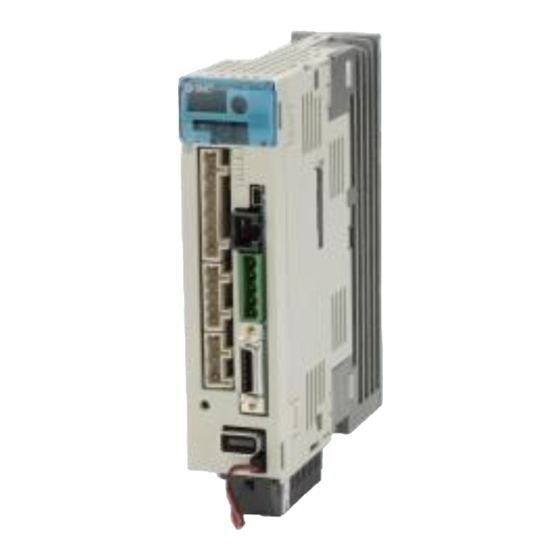
Summary of Contents for SMC Networks LECSC Series
- Page 1 LEC-OM06008 (Doc no. JXC※-OMT0056-A) (Simplified edition) PRODUCT NAME AC Servo Motor Driver (CC-Link Type) MODEL / Series / Product Number LECSC Series...
- Page 2 文書管理 No. - 旧文書体系 No. 対応表 文書管理 No. 旧文書体系 No. JXC※-OMT0056 LEC-OM06007 JXC※-OMT0056-A LEC-OM06008 本書は、対応文書の原紙と一緒に保管する。...
-
Page 3: Table Of Contents
CONTENTS CONTENTS ....................1 Introduction ....................7 1. Configuration .................... 8 2. Pre-Operation Procedure ................9 2.1 Flow chart ........................9 2.2 Driver display ......................10 3. Wiring ......................12 3.1 Power Supply Wiring ....................12 3.2 I/O signal connection ....................13 3.2.1 Connection example (Sink I/O interfaces) ................ - Page 4 5.6.4 Move distance Configuration and Operation ............... 50 5.7 Positioning (Point Table) Operation using the Setup Software ......51 5.7.1 Point table List ......................... 51 5.7.2 Point table Data ........................52 5.7.3 Point table (Target position) Configuration ................53 5.7.4 Point table (Servo Motor Speed) Configuration ..............56 5.7.5 Point Table (Acceleration time constant/Deceleration time constant) Configuration ..
- Page 5 8.1 Point table method ....................112 8.1.1 Positioning operation indication of the point table method (Example) ......112 8.2 Remote register method ..................116 8.2.1 Positioning operation indication of the remote register method (Example) ....116 9. Troubleshooting ..................121 9.1 Alarms and Warning List ..................
- Page 6 LECSC Series / Driver Safety Instructions These safety instructions are intended to prevent hazardous situations and/or equipment damage. These instructions indicate the level of potential hazard with the labels of “Caution,” “Warning” or “Danger.” They are all important notes for safety and must be followed in addition to International Standards (ISO/IEC), Japan Industrial Standards (JIS)*1) and other safety regulations*2).
- Page 7 safety analysis. 4) Use in an interlock circuit, which requires the provision of double interlock for possible failure by using a mechanical protective function, and periodical checks to confirm proper operation. Note that the CAUTION level may lead to a serious consequence according to conditions. Please follow the instructions of both levels because they are important to personnel safety.
- Page 8 LECSC Series / Driver Safety Instructions Caution The product is provided for use in manufacturing industries. The product herein described is basically provided for peaceful use in manufacturing industries. If considering using the product in other industries, consult SMC beforehand and exchange specifications or a contract if necessary.
-
Page 9: Introduction
Introduction It is recommended that the operator read the operation manual for LECSC prior to use. For the handling and details of other equipment, please refer to the operation manual for used equipment. Check that the main circuit power supply (AC100V/AC200V) and controller circuit power supply (AC100V/AC200V) are wired correctly. -
Page 10: Configuration
1. Configuration Minimum equipment and wiring requirements to get started Provided by customer 200 V AC (*1) Provided L1 by customer L2 L3 P1 P2 P L11 L21 (*2) Electric Actuators Ex) LEF Provided by customer PLC (CC-Link master unit) (*1) Refer to “LECSC Operation Manual”, Chapter 4 for further details if the power supply voltage is 100VAC. -
Page 11: Pre-Operation Procedure
2. Pre-Operation Procedure 2.1 Flow chart Wiring See [3. Wiring] Parameter setting See [4. Parameter list (Driver side)] Parameter Settings using the Setup Software (MR Configurator2 see [5. Parameter Settings using the Setup Software (MR Configurator2 Signal allocation setting See [5.5 Changing I/O Signal Allocation] CC-Link setting See [6. -
Page 12: Driver Display
2.2 Driver display On the driver display (three-digit, seven-segment display), check the status of communication with the CC-Link driver at power-on, check the station number, and diagnose a fault at occurrence of an alarm. (1) Display sequence Driver power ON Servo amplifier power ON (Note 3) Waiting for CC-Link communication... - Page 13 (2) Indication list Indication Status Description Power of the CC-Link master module was switched on at the condition that the power of b # # Waiting for CC-Link CC-Link master module is OFF. communication The CC-Link master module is faulty. The servo was switched on after completion of initialization and the driver is ready to operate.
-
Page 14: Wiring
3. Wiring 3.1 Power Supply Wiring Connect the actuator and driver power supply. (1) LECSC (Absolute encoder) EX.) Power supply is AC200V single phase Trouble Emergency stop (Note 6) Driver Servo amplifier Servo motor (Note 7) Controller CNP1 1-phase CNP3 200 to (Note 5) 230VAC... -
Page 15: I/O Signal Connection
3.2 I/O signal connection 3.2.1 Connection example (Sink I/O interfaces) An example of a connection for the I/O signal connection is shown below. Connect wires as necessary. Servo amplifier Driver (Note 4) (Note 2) 24VDC power Ready supply DICOM (Note 9) Trouble (Note 6) DOCOM Home position... -
Page 16: Source I/O Interfaces
3.2.2 Source I/O interfaces It is possible to configure the I/O interface for, source type I/O interface. In this case, all (DI-1) input signals and (DO-1) output signals are of source type. wire according to the following interfaces. (1) Digital input interface DI-1 Driver Servo amplifier EMG,... -
Page 17: Wiring Of Plc And Driver
3.3 Wiring of PLC and driver Connect the PLC and the driver. (1)Wiring of PLC and driver Connect the programmable driver CC-Link master unit station and the driver by a twisted cable (3-wire type). Programmable controller CC-Link unit CC-Link Ver.1.10-compliant cable (2) Wiring of connector The pin layout of the communication connector CN1 on the driver unit is shown below. - Page 18 (3) Connecting multiple units Example for connecting multiple servo units As the remote I/O stations of CC-Link, drivers share the link system and can be controlled/monitored using programmable driver user programs. LECSC□-□ LECSC□-□ MR-J3- T option unit MR-J3- T option unit Programmable controller CC-Link connector (CN1) CC-Link master unit...
-
Page 19: Parameter List (Driver Side)
4. Parameter list (Driver side) Parameters require setting. If necessary, please set the parameters. Refer to "LECSC Operation Manual”,chapter 6 and "LECSC Operation Manual (Simplified Edition)”,section 5.3 for details. Refer to "LECSC Operation Manual",chapter 6 for parameters which are not mentioned. (MR Configurator2 :LEC-MRC2E) is necessary for the setting of parameter. -
Page 20: Parameter Configuration Using Setup Software
5. Parameter Configuration using Setup software (MR Configurator2 This section describes the configuration procedure for main parameters using the setup software (MR : LEC-MRC2E). See chapter 6 of the “LECSC Operation Manual” for parameter details. Configurator2 5.1Setup software (MR Configurator2 *1 Setup software version 1.52E or above is required. -
Page 21: Start Up The Setup Software
5.2.1 Start up the Setup software (MR Configurator2 ① Connect the PC and LECSC using the USB cable. ② Turn on the power of the LECSC. ③ Start application “MR Configurator2”. Once the application starts, the screen below will be displayed. -19-... -
Page 22: System Settings
5.2.2 “System Settings” ① From “Project” menu select “New”, the “New project” window will be displayed. 5.2.3 Model Selection ① The Mitsubishi Electric Corporation series will be displayed in the model selection list. Please select the model “MR-J3-T”, if using the LECSC. Please select the station for the USB connection. -
Page 23: Driver On Line Check
5.2.4 Driver ON LINE Check Check that the driver is enabled (ONLINE). Check that the “ONLINE/OFFLINE” icon is displayed “ ”. It is OFFLINE when displayed as “ ”. * For OFFLine, PC and amplifier aren’t communicating. Confirm the following points. - Is amplifier's power supply turning on? - Are PC and amplifier connected with the USB cable? - Is the USB driver installed? -
Page 24: Parameter Settings (Driver Side)
5.3 Parameter Settings (Driver side) is necessary for setting the parameter. The setup software (MR Configurator2 :LEC-MRC2E) *1 Setup software version 1.52E or above is required. *2 The setup software (MR Configurator2 :LEC-MRC2E) must be purchased as an additional item. *3 The USB cable (LEC-MR-J3USB) must be purchased as an additional item. -
Page 25: Change Of Parameter Block
5.3.1 Change of parameter block To enable settings for all parameters. ① Select “Basic settings (list)” tab and change “PA19” value to “000C”. ② Click the “PA19” row then click “Selected Items Write”. ③ Cycle the power off, then on for parameters for this driver to be enabled. ②... -
Page 26: Parameter Configuration Method (Ex. "Control Mode" Selection)
5.3.3 Parameter Configuration Method (Ex. “Control mode” Selection) Please set the parameters for each actuator. Please change the parameter values according to usage. Refer to "LECSC Operation Manual”,chapter 6 for details of each parameter. Refer to “LECSC Operation Manual (Simplified Edition)”,section 5.4.3 for recommended parameter values for SMC supplied actuators. -
Page 27: Recommended Parameter Values By Actuator Model
5.3.4 Recommended Parameter Values by Actuator Model Please change the parameter values according to the customer application. Refer to “LECSC Operation Manual”,chapter 6 for details. Recommended Parameter Values [LEF] LEFS25 LEFS32 LEFS40 Lead symbol Series Lead Para. Initial Parameter *1,*2 Recommended value value Electronic gear... - Page 28 LEFB25 LEFB25U LEFB32 LEFB32U LEFB40 LEFB40U Series Lead symbol Lead Para. Initial Parameter *1,*2 Recommended value value Electronic gear PA06 32768 numerator *3 Electronic gear PA07 6750 denominator *3 Feel length multiplication (STM) PA05 0000(Less than stroke 1000)/ 0001(Stroke 1000 or more) 0000 (Multiplier) Home position return...
- Page 29 Recommended Parameter Values [LEJ] LEJS40 LEJS63 LEJB40 LEJB63 Series Lead symbol Lead Para. Initial Parameter *1,*2 Recommended value value Electronic gear 32768 PA06 numerator *3 Electronic gear 3000 2000 1000 3750 2500 1250 3375 5250 PA07 denominator *3 Feel length multiplication (STM) PA05 0000(Less than stroke 1000) / 0001(Stroke 1000 or more)
- Page 30 Recommended Parameter Values [LEY] LEY25D/ LEY32D/ LEY25/LEYG25 LEY32/LEYG32 LEYG25D LEYG32D Series Lead symbol Lead Initial Parameter Para. No Recommended value *1,*2 value Electronic gear PA06 32768 numerator Electronic gear 1500 1500 2500 1250 2000 1000 PA07 denominator Feel length multiplication (STM) PA05 0000 (Less than stroke 1000) / 0001 (Stroke 1000 or more) 0000...
- Page 31 LEY63 LEY63D Lead symbol Series Lead 5(2.86) (Including pulley (Pulley ratio 4/7) ratio) Initial Parameter Para. No Recommended value *1,*2 value Electronic gear PA06 32768 57344 32768 numerator Electronic gear 2500 1250 2500 1250 PA07 denominator Feel length multiplication (STM) PA05 0000 (Less than stroke 1000) / 0001 (Stroke 1000 or more) 0000...
-
Page 32: Absolute Position Detection System
5.3.5 Absolute position detection system Select absolute position detection system Set parameter: [PA03] Parameter Initial Unit Setting range value Symbol Name PA03 Absolute position detection system 0000h Refer to the text. POINT This parameter is made valid when power is cycled on after setting. Set this parameter when using the absolute position detection system. -
Page 33: Remote Register-Based Position/Speed Specifying System Selection
5.3.6 Remote register-based position/speed specifying system selection When controlling the actuator in the remote register system, you must choose a method for controlling the position command data and speed command data. Select the remote register-based position / speed specifying system. Set parameter: [PC30] Symbol Name and function... -
Page 34: Electronic Gears
5.3.7 Electronic Gears c It is necessary to adjust the electric gear to convert from the ommand movement value sent from CC-Link smallest unit is 1[μm] (0.001[mm]) master unit to the travel distance ( of electrical actuator. See “LECSC Operation Manual (Simplified Edition)”,section 5.3.4 for the recommended values for electronic gears for each actuator model. -
Page 35: Verify Of Parameters
5.3.8 Verify of parameters If you want to compare the "parameter" set in the setup software with the " Parameters set in the driver" / "Initial value parameter" / "Saved parameter", perform " Verify ". ① Click the “Verify” button on the [Parameter Setting] window. "Verfication Setting" screen will display. ②... -
Page 36: Parameter Initialization
5.3.9 Parameter initialization If you want to initialize parameters in the driver, please perform "Set to Default". When you initialize the parameters, parameters can not be undone. Please be sure to save the parameters in use. (Refer to “LECSC Operation Manual (Simplified Edition)”, section 5.8.1 for the parameter storage method.) ①... -
Page 37: Jog Mode In The Setup Software
5.4 JOG Mode in the Setup Software ① The “JOG Mode” window can be displayed by selecting “Jog Mode” from the “Test Mode” menu in the setup software. ② Click “OK”. (When using this function, all external input signal operation will be diabled. If controlling using a PLC or other upper device, please turn off the power and reset the device before use.) ①... -
Page 38: Jog Mode
5.4.1 JOG Mode ① In order to prevent accidental impact at the end of the stroke, test actuator operation at low speed. See “LECSC Operation Manual (Simplified Edition)”,section 5.6.2 for motor speed configuration. See “LECSC Operation Manual (Simplified Edition)”,section 5.6.3 for Acceleration/deceleration time. ②... -
Page 39: Changing I/O Signal Allocation
5.5 Changing I/O Signal Allocation Input/output signal assignment can be changed as appropriate from initial settings. There may be cases when changes to the Input/output signal assignment are required for actuator operation. Please be aware that any changes will alter signals entered as initial settings. Please allocate it according to your system specification. - Page 40 (1) PD01 : Input signal automatic ON selection 1 If you want to the SON to automatic ON Binary number (BIN) "0100" to Hexadecimal (HEX) "4" Binary number (BIN) "0000" to Hexadecimal (HEX) "0" If you want to the LSP and LSN to automatic ON Binary number (BIN) "1100"...
- Page 41 * Enabling “Stroke end” (LSP, LSN) , “Forced stop” (EMG) and “Servo-on” (SON) Signals ① Set to PD01 to 1C04 in the I/O setting tab. ② Click on the "Single Axis Write" button. ③ Cycle the power for the changed Parameters to be enabled. * In this configuration, the stroke end (LSP, LSN), forced stop (EMG) and servo-on (SON) signals will be ON automatically when the power is turned ON.
-
Page 42: Initial I/O Signal Allocation
5.5.2 Initial I/O Signal Allocation The initial (Default) allocation of I/O signals is shown below. PD06 to PD08 Input signal assignment (CN6-2 to CN6-4) PD09 to PD11 Output signal assignment (CN6-14 to CN6-16) Input signal points (4): (position control mode) and initial assignment Output signal points (3) (position control mode) and initial assignment See “LECSC Operation Manual”, section 3.5.2 and “LECSC Operation Manual”,section 4.5 for details regarding signals. -
Page 43: Allocation Examples
5.5.4 Allocation Examples (1) Example of Clear (CR) Settings Changing pins CN6-2 from Proximity dog (DOG) to Clear (CR). ① Changing PD06 from 002B to 0006 -41-... - Page 44 (2) Symbol allocation using the setup software: Changing pins CN6-2 from Proximity dog (DOG) to Clear (CR). ① Change PD06 from 002B to 0006 in the I/O settings tab. ② Click on the "Single Axis Write" button. ③ Cycle the power off, then on for the parametersto be enabled. ②...
-
Page 45: I/O Signal Allocation Check
5.5.5 I/O Signal Allocation Check The ON/OFF state (including layout check) and signal names allocated to CN6 can be checked. When parameters for PD06 - PD11 have been changed, It is necessary to confirm these are correctly assigned. ① From the Monitor menu of the Setup Software select I/O Monitor. The I/O Monitor window opens and displays the inputs and outputs that are applicable. -
Page 46: Parameter Setting When Using It By I/O Signal (Cn6 Connector Use)
5.5.6 Parameter setting when using it by I/O signal (CN6 connector use) Please configure PD12:External DI function selection 1 and PD14:External DI function selection 3 in Hexadecimal (HEX). When using signal of the servo on (SON) by the I/O signal (CN6) 0100 4 in HEX 0000 0 in HEX 1100 C in HEX... - Page 47 * Enabling “Servo-on” (SON) and “Automatic/manual selection” (MD0) Signals ① Set PD12 to 0C04 and PD14 to 0801 in the I/O setting tab. ② Click on the "Single Axis Write" button. ③ Cycle the power for the changed Parameters to be enabled. ②...
-
Page 48: Positioning Mode In Setup Software
5.6 Positioning Mode in Setup Software ① From the Test Mode menu of the Setup Software select Positioning Mode. The Move Distance Unit Selection window opens. ② Click OK. (When using this function, external input signal operation will be disabled. When controlling from a PLC or upper level device, the power must be turned off and then on.) ③... -
Page 49: Positioning Mode
5.6.1 Positioning Mode ① In order to prevent accidental impact at the end of the stroke, operate the actuator at a low speed initially. When changing speed or movement, increase the values whilst checking operation (Change motor speed, acceleration/deceleration time, movement distance values if required). See “LECSC Operation Manual (Simplified Edition)”,section 5.6.2 for motor speed configuration. -
Page 50: Motor Speed Configuration
5.6.2 Motor speed Configuration <Rotation Speed Configuration> ① Motor speed (r/min) configuration. * r/min (rpm): Indicated motor rotation speed (motor rotations/min) Rotation speed must be between 0 and the allowable speed limit for each actuator. Please be aware that the actuator will not operate if this is set to 0. If the rotation speed is too low, this may cause vibration;... -
Page 51: Acceleration/Deceleration Time Configuation
5.6.3 Acceleration/deceleration Time Configuation < Acceleration/deceleration Time Configuration> ① Acceleration/deceleration time (ms) configuration: The acceleration/deceleration time sets the amount of time (ms) in which a prescribed rotation speed(3000[r/min]) is reached. The acceleration/deceleration time must be set to a value between 0 and the allowable acceleration/deceleration speed for each actuator. -
Page 52: Move Distance Configuration And Operation
5.6.4 Move distance Configuration and Operation < Move distance Configuration> ① Set the move distance [pulse]. Select a value within the stroke range. ② Actuator position will operate using [Forward (CCW)], [Reverse (CW)]. The position at which power is turned ON will be set as the home position, and the actuator will travel the amount set as move distance (check wiring and parameters If operation is not performed correctly). -
Page 53: Positioning (Point Table) Operation Using The Setup Software
5.7 Positioning (Point Table) Operation using the Setup Software This feature is only available in positioning (point table) mode. When positioning using the positioning (point table) mode, the point table (target position, speed data, acceleration time, deceleration time etc.) must be configured. (There are 31 points of point tables to be used when 1 station is occupied and 255 points when 2 stations are occupied.) 5.7.1 Point table List... -
Page 54: Point Table Data
5.7.2 Point table Data By parameters "PA01:Control mode” settings, registration method of data of the point table is different. (1) If the parameter " PA01:Control mode" setting is "0000:Absolute value command system " . Setting Item Unit Description range (1) When using this point table as an absolute value command system, set the target address (absolute value). -
Page 55: Point Table (Target Position) Configuration
5.7.3 Point table (Target position) Configuration < Target position Configuration> ① Please set the parameters as "PA05 (Feed function selection)" and "Feel length multiplication (STM) (Multiplier)". Please change the "PA05 (Feed function selection)". " Feel length multiplication (STM) (Multiplier)" will be automatically scaled. For actuators with a stroke less than 1000mm, set parameter “PA05 (Feed function selection)”... - Page 56 Change of the target position input range 1) Please click on the [Detailed Setting] button in the [Point Table] tab. 2) Please confirmation or change of [Feel length multiplication (STM) (Multiplier)]. 3) Click on the "OK" button. 4) Target position input range varies depending on the set value of [Feel length multiplication (STM) (Multiplier)].
- Page 57 ② Configure position data (mm). Set to a value within the stroke range. ② * If electronic gear parameters (PA06/PA07) are set according to“LECSC Operation Manual (Simplified Edition)”,section 5.3.4. The smallest unit for actuator movement is 1[μm] (0.001[mm]). -55-...
-
Page 58: Point Table (Servo Motor Speed) Configuration
5.7.4 Point table (Servo Motor Speed) Configuration <Rotation Speed Configuration> ① Rotation speed configuration: *r/min (rpm): motor command rotation speed (motor rotations/min) Travel speed (mm/s) must be converted into rotation speed (r/min). See below for the conversion formula. Example using a 20[mm] Lead Actuator with target travel speed of 500[mm/sec] Rotations per second ÷... -
Page 59: Point Table (Acceleration Time Constant/Deceleration Time Constant) Configuration
5.7.5 Point Table (Acceleration time constant/Deceleration time constant) Configuration < Acceleration time constant/Deceleration time constant Configuration> ① Acceleration time constant (ms)/Deceleration time constant (ms) configuration: Acceleration/deceleration (mm/s ) must be converted to the acceleration time constant/deceleration time constant (ms). See below for the conversion formula. Conversion example for a 8[mm] lead actuator driven at an acceleration of 3000 [mm/sec Rated Motor Rotation Speed (mm/s) *Note) -
Page 60: Single-Step Feed
5.7.7 Single-Step Feed In Test mode a single step within point table can be executed. ① From the “Test” menu select “Single-step Feed”which opens a window for “Single-step feed”. (When using this function, external input signal operation will be disabled. If controlling using a PLC or other upper level device, ensure the power is turned off and then on before operation.) ②... -
Page 61: Saving/Loading Parameters
5.8 Saving/Loading Parameters 5.8.1 Saving Parameters ① From the “Parameter Setting” window in the setup software, select “Save As”. ② Please specify location to be saved. ③ Please enter any file name. ④ Click “Save”. Files Saved .prm2 Settings files for parameters PA, PB, PC, PD * Note Always upload current parameters from the driver to the software before saving. -
Page 62: To Load Saved Parameters
5.8.2 To Load saved Parameters ① From the “Parameter Setting” window in the setup software, select “Open”. ② Please specify location of the file. ③ Please select the file you wish to import parameters [.prm2]. ④ Click “Open”. Parameters will be loaded. ①... -
Page 63: Saving/Loading Project
5.9 Saving/Loading Project 5.9.1 Saving Project ① From the “Project” menu in the setup software, select “Save As”. ② Please specify location to be saved. ③ Please enter any file name. ④ Click “Save”. Project will be saved in the specified folder. If you change the drive / path name, it will be saved in the "drive ¥path name ¥... -
Page 64: To Load Saved Project
5.9.2 To Load saved Project ① From the “Project” menu in the setup software, select “Open”. ② Please select the "drive ¥ path name ¥ project name" that you want to read parameters are stored. ③ Please select the file you wish to import project [.mrc2]. ④... -
Page 65: Saving/Loading Point Table
5.10 Saving/Loading Point table 5.10.1 Saving Point table ① From the “Point Table” window in the setup software, select “Save As”. ② Please specify location to be saved. ③ Please enter any file name. ④ Click “Save”. ① ② ④ ③... -
Page 66: To Load Saved Point Table
5.10.2 To Load saved Point table ① From the “Point table” window in the setup software, select “Open”. ② Please specify location of the file. ③ Please select the file you wish to import point table [.ptb2]. ④ Click “Open”. Point table will be loaded. -
Page 67: Acquisition Of Motion Waveform With Graph Monitor
5.11 Acquisition of motion waveform with graph monitor With the setup software (MR Configurator2 : LEC-MRC2E) monitor graph function, the motion waveform during electric actuator operation can be obtained as described below. ① Click “Monitor” - “Graph” of Setup software to display “Graph” window. ①... -
Page 68: Under The Setting Tab: Setting Of The Items To Display The Graph
5.11.1 Under the setting Tab: Setting of the items to display the graph Set the items to display analogue and digital waveform, trigger conditions and time for the horizontal axis of the graph. Click the [Setting] tab of the [Setting] window to set the items to display the waveform, trigger conditions and horizontal axis of the graph. - Page 69 (2) Trigger “Trigger” is a condition which decides the display timing of the graph. If trigger conditions are not satisfied, waveform will not be displayed. ① Click “ “ of [Data] to set the condition. (In general, set the Motor speed.) ①...
- Page 70 (4) Waveform Set the waveform data which will be displayed in the graph. ① Click “ “ of each “Analog” or “Digital” and set the type of waveform to be displayed. ① The analogue and digital waveforms that can be set with LECSC are shown below. ■Analogue waveform Name Function...
- Page 71 Name Function Unit Note Torque equivalent The difference between the torque required driving 0.1% to disturbance the motor and the actually required torque (torque current value) is displayed in torque equivalent to disturbance. Overload alarm The margin until the load reaches the overload 0.1% margin (AL.50, AL.51) alarm level is displayed in %.
-
Page 72: Trigger Wait
5.11.2 Trigger wait When the “Start” button is clicked, the screen will be on stand-by. When trigger conditions are satisfied during the trigger wait, waveforms can be captured and displayed. Click the “Start” button every time measurement fresh capture is required. (The advantage of this method of capturing the waveform is a waveform will not be updated in the case of an incorrect operation.) ①... -
Page 73: Operation Instruction
5.11.3 Operation Instruction When the PLC on the master side sends the operation command, the actuator will operate. When the trigger conditions in 5.11.1 (2) are satisfied, the operation waveforms can be captured. When the time set in 5.11.1 (1) has passed after the acquisition start, the acquisition of the waveforms will complete and waveforms are displayed on the screen. -
Page 74: Saving Of Waveform
5.11.4 Saving of waveform After the waveform is displayed, it is possible to save the data in 3 ways. ① Click the “Save As” button. Select the folder in which the step data is to be saved and save the data. Waveform data file (extension: gpf2) will be prepared. -
Page 75: Display All Monitor List
5.12 Display All Monitor List The method how to obtain the electric actuator condition is described with the display all function of the setup software. ① Click “Monitor” - “Display All” of the setup software to display “Display All” window. ②... - Page 76 Name Function Display range Unit Cumulative Feedback pulses from the motor encoder are feedback pulses counted and displayed. When exceeding 999999999, it returns to zero. -999999999 to pulse Press the [Clear] button to reset the display value to 999999999 0 (zero). Reverse rotation is indicated by a minus (-) sign.
-
Page 77: Cc-Link Setting
6. CC-Link setting CC-Link function of the driver. Wiring and PLC setting must to satisfy the specifications. CC-Link communication functions Communication specifications Item Specifications Power supply 5VDC supplied from driver Applicable CC-Link version Ver.1.10 Communication speed 10M/5M/2.5M/625k/156kbps Communication system Broadcast polling system Synchronization system Frame synchronization system Encoding system... -
Page 78: Station Number Setting
6.1 Station number setting Set the station number of each driver. Station number setting method Set the station number with the station number switches (STATION NO.) on the driver front. The station number that may be set is any of 1 to 64 in decimal. In the initial status, the station number is set to station 1. -
Page 79: Communication Baud Rate Setting
6.2 Communication baud rate setting Setting of communication baud rate. Set based on the transfer baud rate of PLC. Communication baud rate setting Set the transfer baud rate of CC-Link with the transfer baud rate switch (MODE) on the driver front. The initial value is set to 156kbps. -
Page 80: Parameter Setting By Plc
6.4 Parameter setting by PLC Setting of CC-Link parameter by PLC. EX.) When Mitsubishi Electric Corporation) GX works2 , master unit QJ61BT11N is used. When refresh device, X1000, Y1000, W0, or W100, occupies 2 stations. If other equipment is used, refer to the operation manual of the equipment. -78-... -
Page 81: Device
6.5 Device The input signals (input devices) may be used as either the CC-Link or CN6 external input signals. Make selection in parameter No.PD06 to PD11, PD12 and PD14. The output signals (output devices) can be used as both the CC-Link CN6 external output signals. - Page 82 (2) When 2 stations are occupied RXn/RYn: 64 points each, RWrn/RWwn: 8 points each Programmable PC or PLC...etc LECSC Driver (RYn) LECSC Driver Programmable PC or PLC...etc (RXn) (Note) Signal (Note) Signal connector connector Signal name Signal name Device No. abbreviation Device No.
- Page 83 Programmable PC or PLC...etc LECSC Driver (RWwn) LECSC Driver Programmable PC or PLC...etc (RWrn) (Note 1) (Note 1) Signal name Signal name Address No. Address No. RWwn (Note 2) Monitor 1 RWrn Monitor 1 data lower 16 bit RWwn (Note 2) Monitor 2 RWwn Monitor 1 data upper 16 bit RWwn...
-
Page 84: Detailed Explanation Of Input Signals (Input Devices)
6.5.1 Detailed explanation of Input signals (Input devices) The note signs in the remarks column indicates the following descriptions. 1: Can be used as external input signals of CN6 connector by setting parameters No.PD06 to PD08 and parameter No.PD12 PD14. 2: Can be automatic turned ON internally by setting parameters No.PD01 PD04. - Page 85 Device No. Signal name Description 1 station 2 stations Remarks (Device name) occupied occupied Proximity dog In the shipment status, the proximity dog external input signal RYn3 RYn3 (DOG) (CN6-2) is valid. For use in CC-Link, make it usable in parameter No.PD14.
- Page 86 Device No. Signal name Description 1 station 2 stations Remarks (Device name) occupied occupied Monitor output execution When RYn8 (MOR) is turned ON, the following data and signals RYn8 RYn8 demand are set. At the same time, RXn8 turns ON. While RYn8 (MOR) (MOR) is ON, the monitor values are kept updated.
- Page 87 Device No. Signal name Description Remarks 1 station 2 stations (Device name) occupied occupied Position instruction demand When RY(n 2)0 is turned ON, the point table No. or position RY(n 2)0 command data set to remote register RWwn 4/RWwn 5 is set.
- Page 88 Device No. Signal name Description Remarks 1 station 2 stations (Device name) occupied occupied Absolute value/incremental RY(n 2)B is made valid when the remote register-based RY(n 2)B value selection position/speed specifying system is selected with Position/speed specifying system selection (RY(n 2)A) and the absolute value command system is selected in parameter No.PD10.
-
Page 89: Detailed Explanation Of Output Signals (Output Devices)
6.5.2 Detailed explanation of Output signals (Output devices) POINT The output devices can be used for both the remote output and the external output signals of CN6 connector. The signal whose Device No. field has an oblique line cannot be used in CC-Link. Device No Signal name Description... - Page 90 Device No Signal name Description 1 station 2 stations occupied occupied Instruction code execution Refer to Instruction code execution demand (RYn9) (COR). RXn9 RXn9 completion (COF) Warning RXnA (WNG) turns ON when a warning occurs.When no warning has RXnA RXnA (WNG) occurred, RXnA (WNG) turns OFF within about 1s after power-on.
-
Page 91: Detailed Explanation Of Remote Registers Input
Device No Signal name Description 1 station 2 stations occupied occupied Trouble A trouble is assigned to the CN6-15 pin as an external output signal. RX(n 1)A RX(n 3)A (ALM) RX(n 1)A or RX(n 3)A (ALM) turns ON when the protective circuit is activated to shut off the base circuit. - Page 92 Remote register Signal name Description Setting range 1 station 2 stations occupied occupied Refer to "LECSC RWwn+2 RWwn+2 Instruction code Sets the instruction code used to perform parameter or point Operation Manual”, table data read and write, alarm reference or the like. section 3.5.4 (1), (2) Setting the instruction code No.
-
Page 93: Detailed Explanation Of Remote Registers Output
6.5.4 Detailed explanation of Remote registers output Output (Driver Programmable PC or PLC...etc) Note that the data set to RWrn and RWrn+1 depends on whether 1 station or 2 stations are occupied. If you set inappropriate code No. or data to the remote register input, the error code is set to respond code (RWrn+2). -
Page 94: Monitor1 (Rwwn) ・ Monitor2 (Rwwn+1)
6.6 Monitor1 (RWwn) ・ Monitor2 (RWwn+1) To demand 32-bit data when 2 stations are occupied, specify the lower 16-bit code No. Use any of the read instruction codes (0101 to 011C) to read the decimal point position (multiplying factor) of the status indication. -
Page 95: Timing Chart Of Monitor
6.6.1 Timing chart of monitor (1) When 1 station is occupied Monitor 1 (RWwn) Monitor 2 (RWwn+1) Monitor execution demand (RYn8) Monitoring (RXn8) Monitor 1 data (RWrn) Monitor 2 data (RWrn+1) Respond code (RWrn+2) Data HOLD Set the Monitor Code No. (0000 to 001D) to Monitor 1 (RWwn) and Monitor 2 (RWwn+1) and turn Monitor output execution demand (RYn8) to ON. -
Page 96: Pxrogramming Example Of The Monitor
(2) When 2 stations are occupied Monitor 1 (RWwn) Monitor 2 (RWwn+1) Monitor execution demand (RYn8) Monitoring (RXn8) Monitor 1 data Lower 16bit (RWrn) Monitor 1 data Upper 16bit (RWrn+1) Monitor 2 data Lower 16bit (RWrn+5) Monitor 2 data Upper 16bit (RWrn+6) Respond code (RWrn+2) Data HOLD... -
Page 97: Read Instruction Code No. (0000H To 0Affh)
6.7 Read instruction code No. (0000h to 0AFFh) The word data requested to be read with the instruction code No. (0000h to 0AFFh) is read by Read code (RWrn+3). Set the command code No. corresponding to the item to RWrn+2. The codes and answer data are all 4-digit hexadecimal numbers. - Page 98 Read Reading data (RWrn 3) contents instruction Item/Function (LECSC Driver Programmable PC or PLC...etc) code No. 0040h Input device status 0 bit 0 to bit F indicate the OFF/ON statuses of the corresponding input Reads the statuses (OFF/ON) of the input devices.
- Page 99 Read Reading data (RWrn 3) contents instruction Item/Function (LECSC Driver Programmable PC or PLC...etc) code No. 0052h Output device status 2 bit 0 to bit F indicate the OFF/ON statuses of the corresponding output Reads the statuses (OFF/ON) of the Output devices.
- Page 100 Read Reading data (RWrn 3) contents instruction Item/Function (LECSC Driver Programmable PC or PLC...etc) code No. Monitor multiplying factor 0100h Reads the multiplying factor of the data to be read with the monitor code. 011Dh The instruction codes 0100 to 011D Monitor multiplying factor correspond to the monitor codes 0000 to 0003:...
- Page 101 Read Reading data (RWrn 3) contents instruction Item/Function (LECSC Driver Programmable PC or PLC...etc) code No. Servo motor speed of point table No.1 to 255 0601h (1) The servo motor speed set to the requested point table No. is The decimal value converted from the 2 lower returned.
-
Page 102: Timing Chart Of Read Instruction Code
6.7.1 Timing chart of read instruction code Read instruction codes (0000h to 0A1Fh) Instruction code (RWwn+2) Instruction code execution demand (RYn9) Instruction code execution completion (RXn9) Reading data (RWrn+3) Respond code (RWrn+2) Data read period Set the read instruction code (0000h to 0A1Fh) to Instruction code (RWwn+2) and turn Instruction code execution demand (RYn9) to ON. -
Page 103: Write Instruction Code No. (8010H To 91Ffh)
6.8 Write instruction code No. (8010h to 91FFh) Set the data, which was requested to be written with the write instruction code No. (8010h to 91FFh). Set the instruction code No. corresponding to the item to Instruction code (RWwn+2) and the written data to Writing data (RWwn+3). - Page 104 Write Writing data (RWwn 3) contents instruction Item (Programmable PC or PLC...etc LECSC Driver) Code No. Position data RAM command of point table 8401h (1) Convert the values into hexadecimal before setting. Writes the position data of point table No. 1 to 255 to RAM.
- Page 105 Write Writing data (RWwn 3) contents instruction Item (Programmable PC or PLC...etc LECSC Driver) Code No. Position data EEP-ROM command of point 8B01h (1) Convert the values into hexadecimal before setting. table Writes the position data of point table No.1 to 8BFFh (255) 255 to EEP-ROM.
-
Page 106: Timing Chart Of Write Instruction Code
Write Writing data (RWwn 3) contents instruction Item (Programmable PC or PLC...etc LECSC Driver) Code No. Auxiliary function data EEP-ROM command of point table Writes the auxiliary function data of point table 9101h (1) No.1 to 255 to EEP-ROM. Written to EEP-ROM, Convert the values into hexadecimal before setting. -
Page 107: Respond Codes (Rwrn+2)
6.9 Respond codes (RWrn+2) If any of the monitor codes, instruction codes, position command data/point table Nos., speed command data/point table Nos. set to the remote register is outside the setting range, the corresponding error code is set to respond code (RWwn+2). -
Page 108: Home Position Return
7. Home position return Driver has the function to return to origin. The home position return type is set by the driver parameter. When incremental type is selected, returning to home position is necessary every time the input power supply is turned on. -
Page 109: Home Position Return
7.1.1 Home position return Home position return types Choose the optimum home position return according to the machine type, etc. Type Home position return method Features General home position return method using a proximity dog. With deceleration started at the front end of a proximity Repeatability of home position return is dog, the position where the first Z-phase signal is given Dog type home position... -
Page 110: Stopper Type Home Position Return
7.1.2 Stopper type home position return. In stopper type home position return, a machine part is pressed against a stopper or the like by a jog operation to make a home position return and that position is defined as a home position. After completion of stopper type home position return, please move to any position (Not pressed position) from the pressing position. - Page 111 (2) Time chart of stopper type home position return Time chart of topper type home position return. Automatic/manual selection (RYn6) Selected point table No. (Note 1) 6ms or more Forward rotation start (RYn1) 4ms or more Reverse rotation start (RYn2) Torque limit value Parameter No.PC35 (Note 3) Parameter No.PC10...
-
Page 112: Positioning Operation Method Of Operation
8. Positioning operation method of operation The operation method changes depending on the input device, parameter and point table setting. The flow of the operation method that changes depending on the device and parameter setting status is shown in the chart for your reference. - Page 113 Reference Main description "LECSC Manual" Positioning is started by Positioning operation is Section 3.8.2 Point table making the start signal executed once with Section auxiliary function position data handled valid after selection of 5.4.2 (1) as absolute value. the point table with the "LECSC Manual"...
-
Page 114: Point Table Method
8.1 Point table method Positioning is performed according to the point table data (Target position, Rotation speed, Acceleration time constant, and Deceleration time constant) in the driver. (When the point table occupies 1 station, a maximum of 31 points are usable. 255 points become usable when 2 stations are occupied.) See“LECSC Operation Manual (Simplified Edition)”,section 5.7 for Point table data. - Page 115 (4) Selection of point table No. (DI0 to DI7) Device No. Signal name Description Remarks 1 station 2 stations (Device name) occupied occupied Point table No. selection 1 The point table No. and the home position return are selected RYnA RYnA (DI0) by RYnA to RY(n 2)5.
- Page 116 (5) Selection of Forward rotation start (ST1) / Reverse rotation start (ST2) Device No. Signal name Description Remarks 1 station 2 stations (Device name) occupied occupied Forward rotation start (ST1) 1. In absolute value command system RYn1 RYn1 Turning RYn1 ON for automatic operation executes positioning once on the basis of the position data set to the point table.
- Page 117 (6) Timing chart of positioning operation (Point table method) (Ex. Absolute value command system (PA01:0001)) Automatic/manual selection (RYn6) Servo-on (RYn0) Point table No. (Note 2) 4ms or more Forward rotation start (RYn1) (Note 2) 4ms or more 6ms or more Reverse rotation start (RYn2) (Note 1) 3ms or less...
-
Page 118: Remote Register Method
8.2 Remote register method Remote register method of positioning uses the remote register. Set the position and the speed data by the remote register. The constant for acceleration and deceleration is the set value of the point table No.1. This operation is available when two stations are occupied. Refer to "LECSC Operation Manual", section 3.6.3, section 3.8.4, section 5.4.3 for details of the positioning operation program for the remote register method. - Page 119 (2) Selection of command system (PA01) Select the command system. Parameter No.PA01 0 0 0 Selection of command system (Refer to section 5.4) 0: Absolute value command system 1: Incremental value command system (3) Selection of remote register-based position/speed specifying system (PC30) Symbol Name and function Initial value...
- Page 120 (6) Selection of absolute value / incremental value (RY(n+2)B) Device No. Signal name Description Remarks 1 station 2 stations (Device name) occupied occupied Absolute value/incremental RY(n 2)B is made valid when the remote register-based RY(n 2)B value selection position/speed specifying system is selected with Position/speed specifying system selection (RY(n 2)A) and the absolute value command system is selected in parameter No.PD10.
- Page 121 (8) Selection of forward rotation start (ST1) Device No. Signal name Description Remarks 1 station 2 stations (Device name) occupied occupied □□□ 1. In absolute value command system (PA01: Forward rotation start (ST1) 0) RYn1 RYn1 Turning RYn1 ON for automatic operation executes positioning once on the basis of the position data set to the point table.
- Page 122 (9) Timing chart of positioning operation (Remote register method) (Ex. Absolute value command system (PA01:0001) - Absolute value (RY(n+2)B:OFF)) Automatic/manual selection (RYn6) Servo-on (RYn0) Position/speed specifying system selection (RY(n 2)A) Incremental value/absolute value selection (RY(n 2)B) Position data Position data 1 Position data 2 (RWwn 4 RWwn 5) Speed data (RWwn 6)
-
Page 123: Troubleshooting
9. Troubleshooting 9.1 Alarms and Warning List POINT Configure up a circuit which will detect the trouble (ALM) signal and turn off the servo-on (RYn0) at occurrence of an alarm. When a fault occurs during operation, the corresponding alarm or warning is displayed. If any alarm or warning has occurred, refer to“LECSC Operation Manual”,section 10.4.2 or 10.4.3 and take the appropriate action. -
Page 124: Alarm Display
9.2 Alarm Display The contents of the alarm / warning that is currently occurring in the driver are displayed in the alarm display function of the setup software. In addition, history is listed for alarms that occurred in the past. ①... - Page 125 Revision history No.LEC-OM06001 Dec./2012 1st printing No.LEC-OM06002 Dec./2013 2nd printing No.LEC-OM06003 Jul./2014 3rd printing No.LEC-OM06004 Apr./2015 4th printing No.LEC-OM06005 Sep./2015 5th printing No.LEC-OM06006 Dec./2015 6th printing No.LEC-OM06007(No.JXC※ -OMT0056) Sep./2016 10th printing No.LEC-OM06008(No.JXC※ -OMT0056-A) Jun./2017 11th printing 4-14-1, Sotokanda, Chiyoda-ku, Tokyo 101-0021 JAPAN Tel: + 81 3 5207 8249 Fax: +81 3 5298 5362 http://www.smcworld.com Note:...
Need help?
Do you have a question about the LECSC Series and is the answer not in the manual?
Questions and answers