
Related Manuals for SMC Networks LAT3 Series


Summary of Contents for SMC Networks LAT3 Series
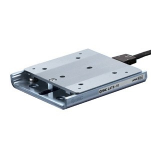
- Page 1 Doc No. LA∗-OMP0023-A PRODUCT NAME Card Motor Model / Series / Product Number LAT3 Series Controller Series LATC4...
-
Page 2: Table Of Contents
Contents Safety Instructions................3 1. Start up procedures / Simple settings for quick start....5 1. 1 Preparation ......................5 1. 2 Controller settings .................... 7 1. 3 Test operation using a computer............... 10 1. 4 Operation by PLC.................... 15 2. - Page 3 6. 7 Operating environment .................. 58 6. 8 Maintenance ...................... 58 7. Common Precautions for wiring and cables ......59 8. Alarm detection ................60 8. 1 Alarm LED display ................... 60 8. 2 Alarms and countermeasures..............61 9. Troubleshooting ................. 62 9.
-
Page 4: Safety Instructions
LAT3 Series/Card Motor Safety Instructions These safety instructions are intended to prevent hazardous situations and/or equipment damage. These instructions indicate the level of potential hazard with the labels of "Caution", "Warning" or "Danger". They are all important notes for safety and must be followed in addition to International ∗1) - Page 5 LAT3 Series/Card Motor Safety Instructions Caution 1. The product is provided for use in manufacturing industries. The product herein described is basically provided for peaceful use in manufacturing industries. If considering using the product in other industries, consult SMC beforehand and exchange specifications or a contract if necessary.
-
Page 6: Start Up Procedures / Simple Settings For Quick Start
The procedures from purchasing to start up using a PLC are explained below. 1. 1 Preparation (1) Items to be prepared Please check the part numbers on the product labels and the quantity of the accessories to confirm that the order is correct. LAT3 series Part No. Description Quantity LAT3∗-∗... - Page 7 (2) Mounting of the Card Motor 【Fixed side / moving side】 Fix the rail to the mounting surface with screws before operating the table. Table 【Mounting surface】 Keep the flatness of the mounting surface of the table and rail 0.02mm or less. Insufficient flatness of a work piece mounted to the table or insufficient flatness of the mounting surface for the rail can cause Rail...
-
Page 8: Controller Settings
(3) Wiring / Connection / Grounding M4 screw Cable with crimped terminal (grounding cable) Shakeproof washer (to be prepared by the user) Actuator cable Counter plug (attached to the controller) Card Motor モ ニ タ モ ニ タ 120.3 120.3 動作中... - Page 9 (2) Basic parameter settings Select the settings in each item described below and register them to the controller by clicking [Setup]. A. [Card Motor Product Number]: Select the product number of the applicable Card Motor. B. [Method to Return to Origin Position]: Select homing method and position.
- Page 10 (5) Settings completed (Download) After the operating conditions have been set in section (4) above, click the [Download to Controller] button (L) to complete the settings. Caution Refer to the LATC4 series (controller) operation manual for details of the data setting procedures and buttons.
-
Page 11: Test Operation Using A Computer
1. 3 Test operation using a computer A test operation can be performed using a computer. The operating performance and the controller settings can be tested and confirmed by operating the Card Motor under the actual operating conditions using the Card Motor Controller Setting Software in “Test Mode” as follows. A. - Page 12 (2) Inching a set distance The Card Motor can be jogged a certain distance at a time as follows. Click the [Servo Off] button to energize the motor. (ii) Click the [Return to Origin] button to move the table to the Origin Position. (iii) Enter the desired inching [Speed].
- Page 13 (3) Step Data Operation The operation of individual step data can be checked in accordance with the procedure below. The operation of each button corresponds with the I/O signals so it is possible to simulate the PLC operation. Press [Servo Off] to energize the motor (equivalent to switching ON the SVON signal). (ii) Press [Return to Origin] to move the table and set the Origin position (equivalent to switching the DRIVE signal ON when the IN0 to IN3 signals are OFF).
- Page 14 (4) Continuous Operation The operation of a continuous cycle can be checked in accordance with the procedure below. A. Selection of Return to Origin Position・・・・・ Select Step “1”, and select the "Return to Origin" option in the ”Step Data Number” column, and tick the "One Time Ope”...
- Page 15 Warning Consider the table movement. If the operation is ended (the motor becomes de-energized). Because no power is supplied to the Card Motor the table will not be fixed and can be moved by external force or by the table’s own weight (including workpieces).
-
Page 16: Operation By Plc
1. 4 Operation by PLC The step data set in the controller can be selected and the Card Motor operated to the steps using the digital I/O signals of a PLC. Complete and download to the controller the “Basic Parameter Setup” and “Step Data Setup” settings before operating the product using a PLC. - Page 17 (2) Parallel I/O connector wiring (Example) ■NPN type ■PNP type 24 VDC 24 VDC power supply power supply for the input for the input signals signals ∗The power ∗The power supply can supply can be either be either polarity. polarity. DRIVE DRIVE SVON...
- Page 18 Caution There are two types of parallel inputs and outputs for this controller; NPN type (LATC4-N ∗∗ ) and PNP type (LATC4-P ∗∗ ). Please confirm the specification before wiring. The 24 VDC power supply for the controller (CN1), and the 24 VDC power supply for the parallel I/O (CN5) should be separate.
- Page 19 (4) Timing chart (Example) The timing chart below shows the sequence of the parallel I/O signals for an example operation after power has been supplied to the controller. Return to Origin position → Step Data No.1 → Step Data No.2 → Operation completed (The motor is de-energized)...
- Page 20 (5) Monitor mode The status of the parallel I/O signals, the table position, speed and pushing force can be monitored in Monitor Mode when the Card Motor is operating using a PLC to control the parallel I/O signals. A. Select "Monitor Mode" in the "Test Mode / Monitor Mode" tab. Test Mode The Card Motor operates based on operation commands from the Controller Setting Software.
-
Page 21: Product Outlines
If the I/O cable is required, please order separately. (Refer to section “3.4 I/O cable” (P.33)) Note 2) The DIN rail is not included. If the DIN rail is required, please order separately. (Refer to the LAT3 series catalogue for details.) - 20 -... -
Page 22: System Structure
2. 2 System structure Note 1) “Options” such as controller and cables can be added to the How to Order for the main products (Card Motor and Card Motor controller). Refer to How to Order for details. Note 2) “Separately sold products” cannot be added to the How to Order for the main products (Card Motor and Card Motor controller). -
Page 23: Specifications
3. Specifications 3. 1 Card Motor (1) Card Motor specifications Model LAT3-10 LAT3F-10 LAT3-20 LAT3F-20 LAT3-30 LAT3F-30 Stroke [mm] Type Moving magnet type linear motor Maximum instantaneous Note 1) Note 2) Note 3) Motor thrust [N] Continuous thrust [N] Note 1) Note 2) Note 3) Type Linear guide with circulating balls Guide... - Page 24 (2) Card motor characteristics Pushing direction Pushing direction Connector side Connector side Opposite side of the connector Opposite side of the connector LAT3*-10 LAT3*-10 Thrust setting value :5 Thrust setting value :5 Thrust setting value :3 Thrust setting value :3 Thrust setting value :1 Thrust setting value :1 Pushing position [mm]...
- Page 25 Card motor Work load LAT3-10 Card moto Work lo LAT3 Travel Trave LAT3-20 direction Mounting Mounting LAT3-30 angle direc angle LAT3-30 0 20 4 0 6 0 8 0 1 0 LAT3-10 , -20 015 30 45 60 75 90 (Horizontal) (Vert LAT3-30 Duty ratio [%]...
- Page 26 (3) Card motor dimensions Note 1) Refer to “Mounting screw specifications and tightening torques” in section “1.1 Preparation” (P.5). Note 2) The length of the part of the dowel pin inserted into the positioning hole should be shorter than the specified depth. Note 3) This drawing shows the Origin Position.
-
Page 27: Controller
Parallel I/O type I/O cable length Without cable Note 1) The DIN rail is not included. If the DIN rail is required, please order separately. (Refer to the LAT3 series catalogue for details.) (2) Controller specifications Item Specifications Control method... - Page 28 (3) Controller parts description Display Description Details Power Normal operation: Green supply/Alarm However, if also the ALM LED is lit or flashes, an error has been LED (Green) generated. In alarm condition: Lit or flashes Alarm LED (Red) The combination of lit or flashing ALM and PWR LED’s indicates the content of an alarm.
- Page 29 (4) Controller Screw mounting type (LATC4- ∗∗ ) DIN rail mounting type (LATC4- ∗∗ D) - 28 -...
- Page 30 (5) Electrical wiring Power supply connector: CN1 The power supply plug is an accessory supplied with the controller. Use the attached power supply plug for connecting a 24 VDC power supply to the controller power supply connector. Terminal Function Description Power supply plug Terminal for the power supply (-) to the controller.
- Page 31 Parallel I/O connector: CN5 ■NPN type ■PNP type 24 VDC 24 VDC power supply power supply for the input for the input signals signals ∗The power ∗The power supply can supply can be either be either polarity. polarity. DRIVE DRIVE SVON SVON ∗...
- Page 32 Caution Use the LATH2- ∗ I/O cable for connecting a PLC to the controller parallel I/O connector. There are two types of parallel inputs and outputs for this controller; NPN type (LATC4-N ∗∗ ) and PNP type (LATC4-P ∗∗ ). Please confirm the specification before wiring.
- Page 33 (6) OUT0, OUT1 The OUT0 and OUT1 output functions can be reconfigured to perform the functions described below in the "I/O Setup" tab of the Controller Setting Software. INP is set as a default for OUT0, and INF for OUT1. INP signal The output turns ON when the Card Motor table is within the INP output range of the ”Target Position”.
-
Page 34: Actuator Cable
3. 3 Actuator cable (1) How to Order L A T H 1 - 1 Cable length (L) (2) Dimensions Card Motor side Controller side Raised area Note) The actuator cable is direction dependent. Connect the Card Motor side of the cable to the Card motor, and vice versa. A small area of the connector is raised on the controller side. -
Page 35: Counter Cable
3. 5 Counter cable (1) How to Order L A T H 3 - 1 Cable length (L) (2) Dimensions Controller side Multi-counter side (3) Wiring diagram Terminal Signal Insulation Counter plug name colour PhaseB White White Blue PhaseA Black Light gray RESET Yellow... -
Page 36: Multi-Counter
3. 7 Multi-counter Refer to the CEU5 series Multi-counter operation manual for details. (1) How to Order C E U 5 Power supply voltage AC100~240V 24 VDC Optional output methods RS-232C RS-232C、BCD Parallel output transistor type NPN open collector output PNP open collector output (2) Specifications Model... - Page 37 (3) Dimensions BCD output connector (4) Wiring diagram Terminal block of the CEU5 Multi-counter Counter plug for the Insulation Name LATC4 controller colour Insulation Name colour Black White PhaseB White PhaseA Blue Light gray DC12V Yellow RESET ― Green F.G. ―...
- Page 38 (5) User instructions When the LATC4 controller executes Step data No.0 (Return to Origin Position), the controller reset signal will go high after the actuator has completed the [Return to Origin Position] operation. The Multi-counter is reset based on this signal and the position will be set to zero. When the [Sensor Origin] homing method is selected, the Origin Position of the sensor will be set to zero.
-
Page 39: Setting And Operation
4. Setting and operation In order to move the Card Motor to a specific position, it is necessary to set the operation patterns in the LATC4 controller using a PC with the controller setting software installed, or using the teaching box. The sequence of the step data set in the controller is programmed and controlled using a PLC connected to the controller. - Page 40 (2) Speed entry method Setting items: Target position [mm] , Speed [mm/s] , Acceleration [mm/s ] , Deceleration [mm/s Load weight [g] To obtain the total travel distance S [mm] in speed Vc Acceleration Aa absolute positioning mode, calculate the difference between the position from where the table travel Total travel starts to the target position.
- Page 41 (3) Movement modes (Absolute positioning, Relative positioning) The target positions can be specified as absolute or relative positions. Absolute positioning The Target Position is determined based on the "Origin Position” at the retracted end. An example is shown below. + direction + direction - direction - direction...
-
Page 42: Return To Origin Position
4. 2 Return to Origin position The Card Motor uses an incremental type sensor (linear encoder) to detect the position of the table. Therefore, it is necessary to return the table to the Origin Position after the power has been switched on. There are three [Return to Origin Position] methods as described below. - Page 43 Returning to Origin Position movements When the Card Motor is commanded to return to Origin, the Card Motor starts moving from the position where it was in the direction set in the controller setting software in the [Basic Parameter Setup] page under [Method to Return to Origin]. Refer to ”(1)” in the figure below. The Card Motor moves to the respective stroke end until it is stopped by the mechanical end stop and waits there for a specific time, until the controller has recognized the position as the mechanical end stop.
-
Page 44: Positioning Operation
4. 3 Positioning operation Cycle Time Entry Method The acceleration and deceleration are automatically calculated by the controller based on the set target position and positioning time. The table moves according to a triangular movement profile (1) and stops at the set target position (2). Speed Entry Method The table moves based on the set acceleration, speed and deceleration according to a trapezoidal movement profile (3) and stops at the set target position (4). -
Page 45: Pushing Operation
4. 4 Pushing operation Cycle Time Entry Method The acceleration and deceleration are automatically calculated by the controller based on the set target position and positioning time. The table accelerates and decelerates according to a triangular movement profile close to the target position (1), thereafter it continues to move at low speed (6 mm/s) until it comes into contact with the work piece (2). - Page 46 Warning Consider possible unexpected movements of the Card Motor in the event of an emergency stop, alarm or power failure. If power is not supplied to the Card Motor due to an emergency stop, if the SVON signal is switched OFF, in the event of an alarm (when the temperature of the Card Motor exceeds 70 or at power failure, the table will not be held in place and may be moved by external forces.
-
Page 47: Measurement
5.5 Measurement The position sensor (encoder) built into the Card Motor detects the travel distance of the table, and measures the dimensions of the workpiece. Reference level (1) Push the tool against the reference 0.000 level, and reset the counter. Controller CEU5 Multi-counter Tool... - Page 48 Judgement Good/Bad and Differentiation of workpieces The area output ranges preset in the controller are compared with the table position, and the AREA output signals are activated by the controller when the table is within the preset range. Based on these output signals the dimension of the workpiece can be judged to be good or bad, and workpieces of different size can be differentiated.
-
Page 49: Card Motor / Specific Product Precautions
5. Card Motor / Specific Product Precautions ® 5. 1 Design / Selection Warning (1) Make sure that you have read and understood this operation manual for the Card Motor and the one for the LATC4 series controller. Handling, usage or operation other than that specified in the operation manuals may lead to breakage, malfunction and operation failure of the product. -
Page 50: Handling Precautions
Caution (1) Operate within the limits of the maximum usable stroke. The stopper will be damaged if the Card Motor is used with a stroke outside the maximum stroke limits. Refer to the Card Motor specifications for maximum strokes. (2) Do not apply a load outside the specifications. The Card Motor should be fitted for the application based on the maximum workload and allowable moments. - Page 51 (2) When there is abnormal temperature rise, burning or smoking, shut off the power supply. (3) Strong magnet warning. In case abnormal operation noise or vibration occurs, the Card Motor may have been improperly mounted or is loose. Unless operation is stopped for inspection, machinery can be seriously damaged.
-
Page 52: Mounting
(11) Do not dent, scratch or cause other damage to the steel ball rolling surface of the table and rail. It will result in play or increased sliding friction. (12) Positioning accuracy, thrust and measurement accuracy may vary after the Card Motor or the workload have been mounted, depending on the mounting conditions and environment. - Page 53 (7) Do not scratch or damage any sliding part by hitting it with an object. The components are manufactured to high precision. Therefore even a slight deformation may cause operation failure. Caution (1) Mount the Card Motor on a base with good cooling performance, for example a metal plate. If the cooling performance is not good enough, the temperature of the Card Motor will increase, which may cause damage.
-
Page 54: Operating Environment
5. 4 Operating environment Caution (1) Avoid use in the following environments. 1. Locations where large amounts of dust or cutting chips are airborne. 2. Locations where the ambient temperature is outside the operating temperature range (refer to the specifications for details). 3.... -
Page 55: Maintenance
5. 5 Maintenance Warning (1) Before performing installation, wiring and maintenance, check for accumulated voltage using a tester at least 5 minutes after the power supply has been switched off. Accumulated voltage can result in electric shock, fire, and injury. Caution (1) Perform regular maintenance and inspections. -
Page 56: Handling Precautions
(5) If there is a risk of fire or personal injury due to abnormal heat generation, sparking, smoke generated by the product, etc., cut off the power supply from this product and the system immediately. 6. 2 Handling Precautions Warning (1) Never touch the inside of the controller and its peripheral devices. -
Page 57: Installation
(4) Set the “Load Mass” value in the controller setting software according to the approximate weight of jigs or work pieces mounted on the Card Motor. If the “Load Mass” value in the controller setting software and the weight of the workload are different, the product may vibrate or the positioning accuracy may be reduced. -
Page 58: Grounding
(4) Use the UL-certified products listed below as direct current power supplies. a) Limited voltage current circuit in accordance with UL508. A circuit which power is supplied by secondary coil of an insulated transformer that meets the following conditions: - Maximum voltage (No load): 30 Vrms (42.4 V peak) or less - Maximum current : 8 A or less (including short circuit) Limited by circuit protector (such as fuse) with the following ratings... -
Page 59: Operating Environment
6. 7 Operating environment Caution (1) Do not use the products in an area where they could be exposed to dust, metallic powder, machining chips or splashes of water, oil or chemicals. Damage and malfunction can result. (2) Do not use the products in a magnetic field. The ambient magnetic field may result in malfunction. -
Page 60: Common Precautions For Wiring And Cables
Caution (1) Reserve sufficient space for maintenance. Design the system so that it allows required space for maintenance. 7. Common Precautions for wiring and cables Warning (1) The power supply to the product must always be switched off before adjusting, mounting, inspection or wiring is done. -
Page 61: Alarm Detection
(9) The speed / pushing force may vary, depending on the cable length, load and mounting conditions etc. If the cable length exceeds 1 m, the speed / pushing force will decrease by a maximum of 10% per 2m. (If the cable length is 5 m: Maximum 20% reduction.) 【Transportation】... -
Page 62: Alarms And Countermeasures
8. 2 Alarms and countermeasures Alarm Recovery Content / Countermeasure name method <Content of error> The internal memory fails. Check if the conditions described below occurs. Turn the power (1) Power supply shut-off during data writing Memory error off and on (2) Power interruption of the power supply voltage again. -
Page 63: Troubleshooting
9. Troubleshooting Refer to the table below for troubleshooting. When none of the causes in the troubleshooting can be confirmed, it is presumed that the product is faulty and normal operation can only be recovered by the replacement of a part. There is a possibility that this product has been damaged due to the operating conditions (problems relating to the application), so please contact SMC to discuss appropriate measures. - Page 64 Controller alarm is generated? Refer to the operation manual of the controller Alarm Refer to the operation manual of the and take appropriate measures. generated controller. Check the type of alarm. → 14. Alarm Detection (P.66) Correct wiring and check if the input / output of each signal are correct.
- Page 65 If the USB driver has not been installed, the installation of the USB driver starts automatically when the conversion unit is connected to the PC. For details of the installation procedure refer to the “LATC-W1 Controller Setting Software Installation Manual". ...
-
Page 66: Position / Speed / Thrust Troubles
9. 2 Position / Speed / Thrust troubles Error Investigation method and the Error Countermeasures Possible location of possible causes Problem causes In case of return to origin position on the Displaced pushing or retracting end position, does from the Check actuator's operation (if foreign matter the actuator travel to the origin position? origin... - Page 67 Check whether data (step data, Turn the power OFF and ON again. Re- input Doesn't parameter) is written correctly. correct data (step data, parameter) again and move to the Data writing Do not turn off the controller input power confirm operation. failure correct or remove the cable while data is being...
- Page 68 Revision history A: Complete revision Revised in November 2012 4-14-1, Sotokanda, Chiyoda-ku, Tokyo 101-0021 JAPAN Tel: + 81 3 5207 8249 Fax: +81 3 5298 5362 http://www.smcworld.com Note: Specifications are subject to change without prior notice and any obligation on the part of the manufacturer. ©...
Need help?
Do you have a question about the LAT3 Series and is the answer not in the manual?
Questions and answers