Advertisement
This repair will require removal of the unit from it's mounting hardware and repairs made on a bench or floor. Refer to the
Owners Manual and/or Installation Poster for proper assembly and carefully read and understand all warnings and cautions
pertaining to the unit.
!
WARNING
BE SURE ELECTRICAL POWER HAS BEEN DISCONNECTED FROM THE INPUT POWER LINES PRIOR TO REMOVING THE
MOTOR COVER.
!
WARNING
ANY AND ALL REPAIRS MADE TO THIS UNIT MUST BE PERFORMED WITH THE DOOR DISCONNECTED FROM THE OPENER
AND IN THE CLOSED POSITION.
1. Pull emergency release cord on carriage to disengage opener to close door if
necessary. (If unable to lower door using opener, use
extreme caution manually closing door. Before pulling
emergency release cord, make certain people and
objects are clear of door opening.)
2. Unplug opener power cord from power receptacle.
3. Open lens cover by pressing outer tabs on both sides
of motor and swing down to remove light bulbs. FIG. 1.
4. Remove wall control and Safe-T-Beam wires from
terminal block located on rear of opener FIG. 1A. Use
small common screwdriver to press in on orange tabs
while gently pulling wires from block. Mark wires to
help facilitate replacement.
5. Remove the cotter pin & clevis from door arm to
separate door from opener. FIG. 2.
6. Remove motor head and rail assembly from mounting
brackets/hardware and set on a clean work surface or floor.
7. Remove the 3-5/16" bolts from rail to motor mount to remove rail. FIG. 3.
FIG. 2.
39187502683
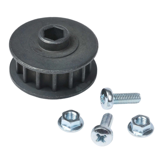
Drive Sprocket Replacement
FIG. 3.
FIG. 1.
Lens Cover Tabs
Wire Tabs
6 5 4 3 2 1
FIG. 1A.
Wall Control 1-2
PhotoCells 3-6
11/2014
Advertisement
Table of Contents

Subscribe to Our Youtube Channel
Related Manuals for Genie 38416A.S


Summary of Contents for Genie 38416A.S
- Page 1 Drive Sprocket Replacement This repair will require removal of the unit from it’s mounting hardware and repairs made on a bench or floor. Refer to the Owners Manual and/or Installation Poster for proper assembly and carefully read and understand all warnings and cautions pertaining to the unit.
- Page 2 8. Loosen 1/2” tension nut at header end of rail to create slack in the FIG. 4 chain/belt. FIG. 4. 9. Place scrap block of wood under the sprocket assembly and drill out the rivets holding the sprocket bracket to the rail with a #7 (.201) drill bit.
Need help?
Do you have a question about the 38416A.S and is the answer not in the manual?
Questions and answers