Advertisement
Quick Links
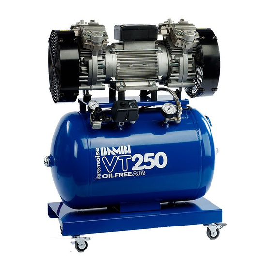
Oil-Free Range Operators Handbook
VT, VTS & VTH models
Covering Models:-
VT75 / VT150 / VT200 / VT250 / VT300 / VT400
VT75D / VT150D / VT200D / VT250D / VT300D / VT400D
VTS75 / VTS150 / VTS200 / VTS250
VTS75D / VTS150D / VTS200D / VTS250D
VTH75 / VTH150 / VTH200
VTH75D / VTH150D / VTH200D
BAMBI AIR LTD
152 Thimble Mill Lane
Heartlands
Birmingham
B7 5HT
Tel: 0121 322 2299
Fax: 0121 322 2297
Email: sales@bambi-air.co.uk
www.bambi-air.co.uk
Advertisement


Need help?
Do you have a question about the VT Series and is the answer not in the manual?
Questions and answers