
Related Manuals for Buhnen HB 5010


Summary of Contents for Buhnen HB 5010
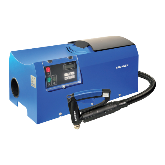
- Page 1 Translation of the original Operating Manual Hot melt adhesive tank system HB 5010 H5307XM (Release 01-2018)
- Page 2 General Security advice Operating Instructions HB 5010 (Basic Unit) Operating Instructions Heatable Hose Operating Instructions Manual Application Unit Declaration of Conformity Spare Parts Lists Maintenance Plan BÜHNEN GmbH & Co. KG Hinterm Sielhof 25 28277 Bremen • Germany Phone: +49 (0) 421 51 20 - 125...
- Page 3 Translation of the original Operating Manual Hot melt adhesive tank system HB 5010 H5307XM (Release 01-2018)
- Page 4 Table of Contents Table of contents Preface “Working safely” ...................... 3 General ............................ 3 Operator’s due diligence ........................3 Recommended personnel ..................... 4 Competent personnel ........................... 4 Instructed personnel ..........................4 Possible hazards ........................4 Notes on safe operation ......................5 Notes on handling the batteries ...................
- Page 5 Preface “Working safely” Preface “Working safely” With the application system, the hot melt material is heated to high temperatures, con- veyed to the application unit and discharged under pressure. This security advice functions as industrial safety and accident prevention. Noncompliance with the security advice can cause burns, injuries, or death by electricity and/or material damage.
- Page 6 Recommended personnel General Security Advice Recommended personnel Activity Requirement Initial operation Competent personnel Facility/Retrofitting Operation Instructed personnel Electrical maintenance/servicing Personnel competent in electrics Mechanical maintenance/servicing Competent personnel Competent personnel Competent persons are those persons having sufficient knowledge in a specific functional area due to their technical training and experience, and who are familiar with the relevant industrial safety and accident prevention provisions as well as the generally acknowledged rules of technology.
- Page 7 - Defective and/or improperly functioning application system. Notes on handling the batteries The HB 5010 tank system control unit has a lithium battery. Please note the following safety notes when handling this battery: • Never cause the battery to short circuit (danger of explosion).
- Page 8 BÜHNEN GmbH & Co. KG Hinterm Sielhof 25 28277 Bremen • Germany Phone: +49 (0) 421 51 20 - 125 Fax: +49 (0) 421 51 20 - 260 kleben@buehnen.de www.buehnen.de...
- Page 9 Translation of the original Operating Manual Hot melt adhesive tank system HB 5010 H5307XM (Release 01-2018)
-
Page 11: Table Of Contents
Special security advice ......................5 Possible dangers ..........................5 Intended use ............................5 Technical data......................... 7 2.1 Product identification ..........................7 Overview of HB 5010 ......................9 Construction ............................9 Function ............................. 10 Operating and display elements ......................11 3.3.1 Main switch ............................... 12 3.3.2... - Page 12 Table of Contents 6.3.3.6 Control parameters ............................30 6.3.3.7 Optimization ..............................31 Set-up / Retrofit ........................33 Removing / Replacing the Housing ....................33 Setting the pump pressure ......................... 34 Changing the hot melt material ......................36 Releasing system pressure ........................ 36 Dismantling a heated hose .........................
-
Page 13: Special Security Advice
The tank system is designed for commercial or industrial use. Only hot melt materials that have been checked and released by the manufacturer may be processed in the HB 5010 tank system. Reactive hot melt adhesives, such as PU (poly- urethane) hot melt adhesives may not be processed. - Page 14 Special security advice...
-
Page 15: Technical Data
35 bar; max. 55 bar Usable tank volume 4.5 liters Noise emission 72 dbA Product identification These operating instructions apply to all HB 5010 basic units with the following illustrated type plate. HB 5010 Teile-Nr.: H530700 el. Anschluß: 220-240V AC / 3400W Ser.-Nr.: 00xxx... - Page 16 Technical data Figure 2.1/2: Location of type plate on the inside of the unit...
-
Page 17: Overview Of Hb 5010
Overview of HB 5010 Overview of HB 5010 Construction The following figures show the HB 5010 tank system and its components with removed housing: Figure 3.1/1: Front view Figure 3.1/2: Back view... -
Page 18: Function
Adjusting screw for pump pressure Connections for hoses (adhesive) Function The HB 5010 hot melt adhesive application system is used for melting and applying adhe- sives (intended use). All components are mounted onto a sturdy console made of sheet steel. The hot melt ad- hesive is filled into the tank (3) in solid form and then melted. The temperature of the hot... -
Page 19: Operating And Display Elements
Overview of HB 5010 The entire system is a modular construction. All electrical connections are pluggable de- signs. This guarantees that all components can be exchanged quickly. All main parameters (temperature, operating conditions) are shown as four-line plain text in the display of the control unit. -
Page 20: Main Switch
Overview of HB 5010 3.3.1 Main switch The entire tank system is turned on and off with the main switch. In the disconnected condition, the system is switched completely to zero current. 3.3.2 Display The display shows the current process values in the normal mode: Time Target and actual values of tank, pump, hose, and pistol temperatures. - Page 21 Overview of HB 5010 Enter This key confirms the entry of a value or the selection of a menu item (using the up/down arrow). Standby By pressing this key, the tank system in manual operation is switched to active standby mode. The temperature of the hot melt material is decreased by a previously programmed value (factory setting: 40 °C) in order to protect the hot melt material (e.g. during work breaks).
- Page 22 Overview of HB 5010 Press “Enter” to definitely turn off the system. Pressing the on/off key again turns the tank system back on. Info! Please note that the tank system will work in the “manually controlled” operating mode in any case after being turned on again by the on/off key, i.e. the tank system will not turn off automatically.
-
Page 23: Installation / Initial Operation
Installation / Initial operation Installation / Initial operation Set-up / Installation 560 mm 820 mm Figure 4.1/1: Required space After unpacking, place the system on a sturdy work surface that will securely bear the weight of the system (38 kg). Lift the unit only by its frame. Leave enough room at the sides (about 50 mm all round) to ensure unobstructed air circu- lation. -
Page 24: First Commissioning
Installation / Initial operation system (see Figure 3.1/2). The following assignment applies: Hose 1 to connection (10), Hose 2 to connection (9). Turn the tank system on. Wait until the hose has reached a temperature of approx. 100 °C. The display at the front of the unit helps to track the temperature. Now screw on the cap nut of the hose by hand onto the corresponding connection of the tank system (see (12) in Figure 3.1/2). -
Page 25: Operation
Operation Operation Filling the hot melt adhesive Figure 5.1/1: Opening the tank lid To fill in the hot melt adhesive, carry out the following work steps: Reach into the recessed grip (2) and swivel the lid (1) towards the direction of the ar- row. Make sure that the tank and the hot melt material is free from impurities and foreign objects. -
Page 26: Standby Operation
Operation Standby operation To protect the hot melt material during temporary work interruptions (e.g. breaks), the tank system can be set into standby operation. The temperature of the hot melt material is decreased by a pre-set value (factory setting: 40 °C). By pressing the “standby”... -
Page 27: Turning Off In Manually-Controlled Operation
Operation Press the “Enter” key. All heaters and controllers are switched off. The control lamps of the main and pump switches remain lit; the display extinguishes. The control unit remains in operation and will turn the tank system back on at the next programmed time. - Page 28 Operation...
-
Page 29: Programming
Programming Introduction The entire HB 5010 tank system programming is done using a clearly structured menu. The required messages and entries are depicted in a four-line display in plain text. Re- lated functions are consolidated in one menu item each and can be quickly accessed. -
Page 30: Navigation
Programming Level 1 (Worker) 1 SingleOnOff 2 Mode Level 2 (Foreman) 3 Language/Sprache default: 1234 4 Password 4 Temperature 5 Timecontrolled 6 Date / Time Level 3 7 System (Trained Service Personnel only) 8 Factory set up 9744 9 Password 9 Maxvalues 10 Waiting Time 11 Settings Pump... -
Page 31: Menu Description
Programming Menu description 6.3.1 Level 1 menu items 6.3.1.1 Individual shutdown Pump: Hose 1: Gun 1: Hose 2: Figure 6.3.1/1: “Individual shutdown“ Not connected or not required components can be individually turned on and off. Shut down components will not be heated. In normal operation, a component is automatically detected and activated after it has been connected. -
Page 32: Password
Programming 6.3.1.4 Password Password * * * * Figure 6.3.1.4/1: “Password“ You can enter the four-digit passwords for Levels 2 and 3 here. Select each digit with “Up/Down Arrow” and confirm the digit with “Enter.” After entering the Level 2 password, 5 additional menu items can be selected (see Chap. 6.3.2) and after entering the main password (Level 3), all menu items can be selected (see Chap. -
Page 33: Time Operation
Programming 6.3.2.2 Time operation ON: 11:15 OFF: 17:30 AN: 06:15 OFF: 17:30 ON: 00:00 OFF: 00:00 StandbyON: 00:00 StandbyON: 12:00 StandbyON: 00:00 StandbyOFF: 00:00 StandbyOFF: 12:30 StandbyOFF: 00:00 Figure 6.3.2.2/1: “Time operation“ The switching times for the time-controlled operation are specified here for every day of the week: • Day (ON/OFF) • Turn on time (ON) •... -
Page 34: System
Programming 6.3.2.4 System Password **** Operation:00098h Display: Power Figure 6.3.2.4/1: “System” You can change the password for menu level 2 here. In addition, the following system data is displayed: • Number of operating hours (“Operation”) • Version number of display electronics (“Display”) •... -
Page 35: Level 3 Menu Items
Programming 6.3.3 Level 3 menu items 6.3.3.1 Limit values Tank Pump Gun 2 High: High: High: Low: Low: Low: Max: Max: Max: Figure 6.3.3.1/1: “Limit values“ The (temperature) limit values (“High”, “Low”, “Max”) are specified here for the compo- nents: • Tank • Pump • Hose 1 / Gun 1 • Hose 2 / Gun 2 A submenu is available for each component (see Figure 6.3.3.1/1). -
Page 36: Waiting Time
Programming Hose 1 Act=185 Set=170 Maximum temperature Confirm with Enter Figure 6.3.3.1/4: “Maximum temperature exceeded“ (Example) Switching off the heaters due to overtemperature can have two causes: While the unit was in operation, a target temperature was programmed (by accident) that was more than (T ) below the current actual temperature. - Page 37 Programming Switch code Function Manual unit coding Pump responds to manual units of all tank systems (only useful for test operation) 1 2 3 4 Pump responds to manual units with switching code “1” 1 2 3 4 Pump responds to manual units with switching code “2”...
-
Page 38: Celsius / Fahrenheit
Programming 6.3.3.4 Celsius / Fahrenheit 0_> Celsius Fahrenheit Figure 6.3.3.4/1: “Celsius / Fahrenheit“ You can select the temperature unit that will be used for all displays and entries here. Conversion occurs automatically. 6.3.3.5 Sensor selection 0_> PT100 NI120 Figure 6.3.3.5/1: “Sensor selection“ Select the type of the temperature sensors used in the hoses and manual units here. -
Page 39: Optimization
Programming 6.3.3.7 Optimization _ Tank Pump Hose1 Gun1 Figure 6.3.3.6/1: “Optimization” This menu item enables the automatic determination and setting of the (PID) controller parameter for the components • Tank • Pump • Hose 1 • Gun 1 • Hose 2 •... - Page 40 Operation...
-
Page 41: Set-Up / Retrofit
Set-up / Retrofit Set-up / Retrofit Removing / Replacing the Housing Required tools: • Slotted screwdriver 10 mm Danger of burns due to hot metal parts, hot melt material, and hot melt material vapors. Therefore, always wear heat protection gloves during the following work steps. Figure 7.1/1: Releasing the housing screws Removing/replacing the housing is only required for maintenance and repair works. -
Page 42: Setting The Pump Pressure
Set-up / Retrofit Setting the pump pressure Required tools • Socket wrench size 8 or • offset box wrench size 8 depth gauge • (metal) measuring stick Danger of burns! The bypass valve used to set the pump pressure can reach temperatures of more than 200 °C. - Page 43 Set-up / Retrofit standard setting Thread length „L“ [mm] Figure 7.2/2: Diagram for setting the pump pressure Adjust the required thread length “L” with wrench size 8.
-
Page 44: Changing The Hot Melt Material
Set-up / Retrofit Changing the hot melt material Make sure first that only a small amount of the old hot melt material is in the tank. Before changing a product, inform yourself whether the old and new hot melt materials are compatible. If the products are compatible, the old hot melt material can be rinsed out with the new material. -
Page 45: Maintenance / Servicing
Maintenance / Servicing Maintenance / Servicing Danger! Maintenance and service works may only be implemented by competent personnel. Disregarding this note can cause damage to the tank system and/or injuries to the per- sonnel. Maintenance intervals Interval Activity Daily Check the tank system for completeness Check all mechanical and electrical connections for tight fit. -
Page 46: Replacing The Back-Up Battery
Maintenance / Servicing Replacing the back-up battery Required tools: • 1 hexagon socket wrench size 3 Spare part: • Lithium battery Varta CR 2032 or identical (3 V) The control unit of the tank system has a back-up battery for the internal realtime clock. This back-up battery lets the realtime clock run even if the tank system is not connected to the power supply or has been disconnected. - Page 47 Maintenance / Servicing The back-up battery is located in the front area of the display circuit board (see following image) Figure 8.3/3 Removing screws and antenna Figure 8.3/3 Position of back-up battery Explosion hazard! While removing and replacing the back-up battery, never touch the bat- tery with tongs or other conductive tools.
-
Page 48: Inspection And Replacement Of Fuses
Maintenance / Servicing Slightly bend the contact spring of the battery bracket towards you. Place the new battery at a slight angle into the bracket. Then swing the battery into the correct (up- right) position in the bracket. In any event, observe correct polarity of the battery (plus pole points towards unit interior)! Figure 8.3/5: Polarity of back-up battery Close and screw on the front panel of the control unit. - Page 49 Maintenance / Servicing Figure 8.4/2 and the following table show the position and assignment of the fuses F1…F8. All fuses are commercially available miniature fuses (5 x 20mm). Figure 8.4/2: Position of fuses on the power section Fuse Value Function 4 A FF (quick acting) Pump motor 0.63 A M (medium time-lag)
-
Page 50: What Happens If
What happens if… What happens if… For occurring malfunctions and faults, first check • the power supply and all electrical connections • whether the main switch and the pump switched have been turned on • whether the temperature values for the utilized hot melt adhesive have been set cor- rectly If defects occur, a protective circuit protects the tanks in any case from being heated to temperatures exceeding 260 °C. -
Page 51: Error Messages In The Display
What happens if… Error messages in the display Display Cause Remedy The temperature of the displayed • Check whether the default component (here: “Hose 1“) has value for the target tempera- Hose 1 exceeded the permissible temper- ture during running operation Act=180 Set=170 Overtemperature... - Page 52 What happens if… Display Cause Remedy The cooling element in the control Turn off the tank system and allow unit has exceeded the permis- it to cool down. If the error occurs Power sible maximum temperature. The again after 30 minutes, notify Overtemperature message must be confirmed with Service.
-
Page 53: Accessories
Spray-air adapter kit 10.1.1 Overview The spray-air adapter kit is required for the “spray” models of the HB 5010 tank system. It regulates, cleans, and dewaters the compressed air required for “spray” operation. Additional requirements for spray operation are: • Heatable “spray” hoses •... -
Page 54: Assembly
Accessories 10.1.2 Assembly Figure 10.1.2/1: Assembly of spray-air adapter kit To assemble the spray-air adapter kit to the tank system, implement the following steps: Insert the supplied fastening screws through the holding plate. Slide the spacer sleeves onto the screws inserted through the holding plate. Screw on the spray-air adapter kit as shown in Figure 10.1.2/1. -
Page 55: Maintenance
Accessories 10.1.4 Maintenance Maintenance of the spray-air adapter kit is limited to the daily draining of the inspection glass which collects the precipitated water from the supplied compressed air. max. level push to empty Figure 10.1.4/1: Spray-air adapter kit maintenance... -
Page 56: Repairs
Repairs Repairs Repairs other than those described in these operating instructions may only be imple- mented by competent persons commissioned by the manufacturer or otherwise competent persons under utilization of original BÜHNEN spare parts. Warranty The unit was developed and manufactured according to the latest state of technology. The first purchaser receives warranty on function, material, and processing according to statu- tory regulations. - Page 57 Repairs...
- Page 58 BÜHNEN GmbH & Co. KG Hinterm Sielhof 25 28277 Bremen • Germany Phone: +49 (0) 421 51 20 - 125 Fax: +49 (0) 421 51 20 - 260 kleben@buehnen.de www.buehnen.de...
- Page 59 Translation of the original Operating Manual Operating Instructions Hot melt adhesive tank system Heatable hose HP Standard HB 5010 H5307XM (Release 01-2018)
- Page 61 Table of Contents Specific security advice ......................5 Possible dangers ..........................5 Intended use ............................5 Notes on safe operation ........................5 Technical Data ........................7 Type key / Available Versions ....................... 7 Technical data ............................7 Dimensioned drawings ......................... 8 Pin assignment ............................. 9 Construction and Function ....................
- Page 62 Table of Contents Table of contents...
-
Page 63: Specific Security Advice
Specific security advice Specific security advice Possible dangers Danger of burns due to hot metal parts, hot melt material, and hot melt material vapors. Therefore, always wear heat protection gloves. Intended use Heatable hoses are used as flexible connections between machines or machine parts. They are used to transport melted hot melt material, such as from a tank system to the manual application unit. - Page 64 Specific security advice...
-
Page 65: Technical Data
Technical Data Technical Data Type key / Available Versions HP_ _ _ _ xx Length Version 24 = 2.4 m without = Protection hose 30 = 3.0 m from braid 45 = 4.5 m = 200 °C HT = High temperature Ø... -
Page 66: Technical Data
Technical Data Dimensioned drawings 600 mm 50 mm 70 mm Ø 4.5 mm Figure 2.3/1: Dimensioned drawing, Extrusion Version 600 mm 50 mm 70 mm Ø 4.5 mm 100 mm 800 mm Figure 2.3/2: Dimensioned drawing, Spray Version... -
Page 67: Pin Assignment
Technical Data Pin assignment Pin type: AMP 14-pole, pins Figure 2.4/1: Pin assignment Color Function brown Heater Hand unit (N) free blue Heater Hand unit (L1) grey Sensor hand unit (Pt100) green/yellow Protective Earth (PE) grey Sensor hand unit (Pt100) free free free... - Page 68 Technical Data...
-
Page 69: Construction And Function
Construction and Function Construction and Function Construction Figure 3.1/1: Mechanical construction of hose (Extrusion Version) Figure 3.1/2: Mechanical construction of hose (Spray Version) Ser. No. Designation Protective braid Silicone foam Brush shunts Insulation (fiberglass braid) Heating conductor Stainless steel fiber Adhesive hose Temperature sensor Pt100 End caps Connection fittings (steel, galvanized), size 19 Connector plug (AMP 14-pole) -
Page 70: Function
Construction and Function Function The basis of the heatable hoses is the adhesive hose (7) through which the hot melt material flows. The hose consists of high-quality PTFE with a smooth surface. Since the adhesive hose does not have great compressive strength it is covered by a stainless steel fiber braid (6). The connection fittings of galvanized steel are pressed with the entire construction. The heating conductors (5) consist of high-quality heating conductor alloys that are covered by a protective conductor braid. -
Page 71: Installation
Installation Installation Attention! The heatable hose may only be installed by competent personnel. See the operating instructions of the tank system for more details. Connection / Removal Assembling the heatable hoses to the tank system is described in detail in the operating instructions of the tank system. -
Page 72: Further Tips On Hose Guidance
Installation 4.2.2 Further tips on hose guidance Wrong Right By pulling the ends of rolled up hoses, torsion stress Unwind the ring. (Do not pull off the hose) occurs. The smallest permissible bending radius can be undercut! Plan to leave a straight piece (length approx. 5 x A too short hose will buckle at the connection ends hose diameter) at the connection ends. - Page 73 Installation Wrong Right Guidance clips can cause buckling to the hose and Remedy: Use a saddle or deflection pulley with bending stress. corresponding diameter. An unfavorable installation will let the hose sag. Remedy: Spiral hose suspension Heat accumulation can occur when laying the hoses in a closed canal or duct. The hoses may not touch each other.
- Page 74 Installation Wrong Right Lay these hoses far enough apart. Bundling or laying the hoses with contact will lead to overheating at these contact sites. Squeezing the hoses caused by brackets can Select the bracket with the matching diameter. damage the hoses. Tighten the bracket enough so that the hose is secured but not squeezed.
-
Page 75: Maintenance
Maintenance Maintenance Attention! Maintenance works may only be implemented by competent personnel. Maintenance intervals Interval Activity Daily Check the hoses for leak tightness. Check all mechanical and electrical connections for tight fit. Remove hot melt material residues and other incrustations. Cleaning Attention! Do not use any aggressive solvent or combustible cleaning agents to clean the hoses. - Page 76 Maintenance...
-
Page 77: Repairs
Repairs Repairs Repairs other than those described in these operating instructions may only be implemented by competent persons commissioned by the manufacturer or otherwise competent persons under utilization of original BÜHNEN spare parts. Warranty The unit was developed and manufactured according to the latest state of technology. The first purchaser receives warranty on function, material, and processing according to statutory regulations. - Page 78 BÜHNEN GmbH & Co. KG Hinterm Sielhof 25 28277 Bremen • Germany Phone: +49 (0) 421 51 20 - 125 Fax: +49 (0) 421 51 20 - 260 kleben@buehnen.de www.buehnen.de...
- Page 79 Translation of the original Operating Manual Manual Application Unit with Radio Control HB 910 Bead / Spray H5307XM (Release 01-2018)
- Page 81 Table of Contents Specific safety instructions ....................5 Potential hazards ..........................5 Scope of use ............................5 Technical data......................... 7 2.1 Product identification ..........................7 Circuit diagram ............................. 8 Construction and function ....................9 Construction bead version ........................9 Construction spray version ......................... 10 Function .............................
- Page 82 Inhaltsverzeichnis...
-
Page 83: Specific Safety Instructions
Specific safety instructions Specific safety instructions Potential hazards Burn Hazard due to hot metal parts, hot melt material, and hot melt material vapors. Therefore, always wear heat protection gloves. Scope of use The manual application unit is for the melting and metered discharge of melts (thermopla- stic substances such as hot-melt adhesives, waxes, etc.) as a bead or spray-on coating. - Page 84 Specific safety instructions...
-
Page 85: Technical Data
Technical data Technical data Model HB 910 HB 910 for bead application for spray application Power supply 230 VAC / 50 to 60 Hz Weight approx. 850 g approx. 770 g Heating capacity 120 W Protection IP30 (in acc. with DIN IEC 34 Protection class (in acc. -
Page 86: Circuit Diagram
Technical data Circuit diagram Supply cord 230 V/ 50 Hz Fig. 2/2: Circuit diagram... -
Page 87: Construction And Function
Construction and function Construction and function Construction bead version Fig. 3/1: Mechanical construction of the manual application unit bead version Designation Heatable hose, type HP standard Connection fittings Protective earth terminal Connection terminal Temperature sensor Heating cartridge Heating cylinder Nozzle UNF 3/8 Nozzle holder Suspension eye Nozzle needle... -
Page 88: Construction Spray Version
Construction and function Construction spray version Fig. 3/2: Mechanical construction of the manual application unit spray version Designation Designation Heatable hose type HP standard Air cap Connection fittings Swirl nozzle Protective earth terminal Suspension eye Connection terminal Nozzle needle Spray air hose with connection Transmitting antenna Temperature sensor Trigger... -
Page 89: Function
Construction and function Function The manual application unit consists of a rigid part permanently connected with the heat- able hose and a rotating part. The part connected with the heatable hose contains • the heater, • the temperature sensor, and •... - Page 90 Construction and function...
-
Page 91: Initial Operation
Initial operation Initial operation Attention! Initial operation may only be implemented by competent personnel. Installation The manual application unit is permanently connected with a heatable hose upon delivery. After the heatable hose has been assembled to the basic unit, the manual application unit is immediately operational without requiring additional measures. - Page 92 Technical data...
-
Page 93: Operation
Operation Operation Attention! Operation may only be implemented by competent personnel. General notes Wear safety gloves! Danger of burn injuries due to hot metal parts, in the area of the heat insulation (21), and due to the discharged hot melt material. To avoid burning yourself while operating the manual application unit, always wear heat protection gloves. -
Page 94: Setting The Spray Pattern (Spray Version Only)
Operation Setting the spray pattern (spray version only) The spray pattern depends on the operating pressure of the tank system and the setting of the spray air pressure. Determine the optimum setting by turning the adjusting wheel at the spray air adapter kit and repeated trials. -
Page 95: Set-Up / Retrofit
Set-up / Retrofit Set-up / Retrofit Attention! Setting up and retrofitting works may only be implemented by competent personnel. Replacing the nozzle Wear safety gloves! Danger of burns due to hot metal parts and due to discharged hot melt material. To avoid burning yourself while setting up/retrofitting the manual application unit, always wear heat protection gloves. 6.1.1 Nozzle UNF 3/8 (bead version) Required tool: 1 open-end wrench size 11 1 box wrench size 11, offset Nozzle Nozzle holder... -
Page 96: Assembling/Dismantling The Heatable Hose
Set-up / Retrofit Remove the air cap. Unscrew the swirl nozzle. Screw on the new swirl nozzle by hand first. Wait about 2 minutes until the new swirl nozzle has been thoroughly heated. Tighten the new swirl nozzle without using force. Replace the air cap. Tighten the retainer ring without using force. Assembling/dismantling the heatable hose Wear safety gloves! Danger of burns due to hot metal parts and due to discharged hot melt material. - Page 97 Set-up / Retrofit Remove the spray air hose from the spray air adapter kit of the tank system. Release the fastening screws (4 pieces) of the heat insulation with the Phillips screw- driver. Remove the heat insulation consisting of 2 half-shells. Release the electrical connections on the hose side as follows: •...
-
Page 98: Setting The Preliminary / Secondary Air
Set-up / Retrofit Setting the preliminary / secondary air Danger of electric shock! Disconnect the power plug from the tank system before carrying out the following work: Connecting and terminating electrical connections may only be implemented by compe- tent electricians. Required tool: 1 Phillips screwdriver 1 Allen wrench size 2.5 Needle carrier... -
Page 99: Setting The Switching Code
Set-up / Retrofit Setting the switching code Required tool: 1 Phillips screwdriver 1 small slotted screwdriver Triggering the pump in the basic unit is controlled by a transmitter in the hand unit. So that the basic unit only responds to the manual application units that are connected to this basic unit, the transmitter and basic unit must be set to the same switch code. - Page 100 Set-up / Retrofit Switch code Function Manual unit coding Pump responds to manual units of all tank systems 1 2 3 4 Pump responds to manual units with switching code “1” 1 2 3 4 Pump responds to manual units with switching code “2” 1 2 3 4 Pump responds to manual units with switching code “3”...
-
Page 101: Maintenance / Servicing
Maintenance / Servicing Maintenance / Servicing Attention! Maintenance works may only be implemented by competent personnel. Maintenance intervals Interval Activity Daily Check the manual application unit for leak tightness, the existence of all parts, and for rm seat of plug and screw connections. -
Page 102: Replacing The Transmitter Battery
Maintenance / Servicing Replacing the transmitter battery Required tool: 1 Phillips screwdriver Required material: 1 lithium battery 3 V, design CR 2032 – Fig. 7/1: Replacing the transmitter battery To replace the transmitter battery, carry out the following work steps: Release and remove the Phillips head screw as illustrated in Figure 7.1. -
Page 103: What Happens If
What happens if… What happens if… For occurring malfunctions and faults, first check • the power supply and all electrical connections • whether the main switch and the pump switched have been turned on • whether the temperature values for the utilized hot melt adhesive have been set correctly Fault Possible cause... - Page 104 What happens if…...
-
Page 105: Accessories
Accessories Accessories Adapter for bead application (spray version only) By installing this adapter (order no. FDH 0423) bead application is possible with the spray version manual application unit as well. The adapter is designed for nozzles with UNF 3/8” threads. 9.1.1 Converting to bead application Wear safety gloves! - Page 106 Accessories Repairs Repairs other than those described in these operating instructions may only be imple- mented by competent persons commissioned by the manufacturer or otherwise competent persons under utilization of original BÜHNEN spare parts. Warranty The unit was developed and manufactured according to the latest state of technology. The first purchaser receives warranty on function, material, and processing according to statu- tory regulations.
- Page 107 Accessories...
- Page 108 BÜHNEN GmbH & Co. KG Hinterm Sielhof 25 28277 Bremen • Germany Phone: +49 (0) 421 51 20 - 125 Fax: +49 (0) 421 51 20 - 260 kleben@buehnen.de www.buehnen.de...
- Page 109 Declaration of Conformity Translation of the original Operating Manual Hot melt adhesive application system Hot melt adhesive tank system HB 5010 HB 5010 H5307XM (Release 01-2018)
- Page 110 Ersatzteillisten...
- Page 111 We, the D-28277 Bremen declare on our sole responsibility that the product Hot melt adhesive application system Type HB 5010 to which this declaration refers, complies with the following Standards or normative documents in its supplied condition: EN ISO 12100-1, -2...
- Page 112 BÜHNEN GmbH & Co. KG Hinterm Sielhof 25 28277 Bremen • Germany Phone: +49 (0) 421 51 20 - 125 Fax: +49 (0) 421 51 20 - 260 kleben@buehnen.de www.buehnen.de...
- Page 113 Translation of the original Operating Manual Hot melt adhesive tank system Hot melt adhesive tank system HB 5010 HB 5010 H5307XM (Release 01-2018)
- Page 114 Table of contents Table of contents HB 5010 Tank System (basic unit) ..................3 Manual application unit ....................... 12 Bead version ............................12 Spray version ............................. 14 Spare parts bead and spray ....................... 16 Wiring diagram ........................19 Operation modes ..........................20...
-
Page 115: Hb 5010 Tank System (Basic Unit)
Spare parts list HB 5010 Tank System (basic unit) Fig. 1/1: Spare parts for basic unit, Part 1... - Page 116 Spare parts list Fig. 1/2: Spare parts for basic unit, Part 2 HB 5010 Tankanlagen Teile- N r./ C ode N o.: H530600X H 530600X 02.02.201 7 1 3:56 D ruck: Zeichnungs- N r.:...
- Page 117 Spare parts list Spare parts for basic unit Item Order No. Quantity Designation H503100 Spray-air adapter kit H530078 Outlet with connection cable H530082 Connection cable pump heater H530083.2 Temperature sensor pump H530086 Connection cable motor H530127 Tank seal H530303 Console H530305 Holding plate H530307...
- Page 118 Spare parts list Fig. 1/3: Spare parts for basic unit, housing with attachments Spare parts for basic unit (housing with attachments) Item Order No. Quantity Designation H530015 Clamp H530077 Protective lid with magnet H530618 Housing complete...
- Page 119 Spare parts list Fig. 1/4: Spare parts for basic unit, hot melt tank Spare parts for basic unit (hot melt tank) Item Order No. Quantity Designation H530306 Stud bolt H530334 Hot melt tank H530346 Stud bolt H530640 Connection block complete H530650 Gear wheel pump complete KDN0555...
- Page 120 Spare parts list Fig. 1/5: Spare parts for basic unit, connection block Spare parts for basic unit (connection block) Item Order No. Quantity Designation H530047 Bypass movement H530341B2 Connection block H530342 Base of valve stem H530343 Valve cone KDN0555 Screw DIN 912 KDN0703 Washer KDN0910...
- Page 121 Spare parts list Sealing set including KDN1024 LDH0132 H530354B LDN0167 KDN0868 Fig. 1/6: Spare parts for basic unit, gear wheel pump Spare parts for basic unit (gear wheel pump) Item Order No. Quantity Designation H530354B Sealing flange H530356B Cover KDN0868 Screw KDN1024 Adjustment spring LDH0132...
- Page 122 Spare parts list Maintenance unit, complete, including Fig. 1/7: Spare parts for basic unit, spray-air adapter kit Spare parts for basic unit (spray-air adapter kit) Item Order No. Quantity Designation ADM0529 Angle bracket H530079 Spacing disc KDN0524 Washer KDN0738 Screw MCH0215 PUR air hose Nw4 MCH0247...
- Page 123 Spare parts list Fig. 1/8: Spare parts for basic unit, housing and tank lid Spare parts for basic unit (housing and tank lid) Item Order No. Quantity Designation H530104 Housing cover H530107 Tank lid H530125 Sealing plate H530148 Sealing plate KDN0783 KDN1038 Hexagon nut...
-
Page 124: Manual Application Unit
Spare parts list Manual application unit Bead version 10 25 6 5 , 7 tighten nut with 25 Nm Fig. 2/9: Spare parts manual application unit, bead version... - Page 125 Spare parts list Spare parts manual application unit (bead version) Item Order no. Quantity Designation FD0241 Nozzle long 0.8 mm FD0242 Nozzle long 1.0 mm FD0243 Nozzle long 1.2 mm FD0244 Nozzle long 1.5 mm FD0245 Nozzle long 2.0 mm FD0246 Nozzle long 3.0 mm H105420...
-
Page 126: Spray Version
Spare parts list Spray version 23 15 26 10 clearance approx. 65.7 approx. 1 mm tighten nut with 25 Nm Fig. 2/10: Spare parts manual application unit, spray version... - Page 127 Spare parts list Spare parts manual application unit (Spray version) Item Order no. Quantity Designation FDH0405 Air cap FDH0406 Coupling ring FDH0407 Swirl nozzle 0.8 mm FDH0408 Swirl nozzle 1.0 mm FDH0409 Swirl nozzle 1.5 mm FDH0410 Swirl nozzle 2.0 mm H105505 Flap H105520...
-
Page 128: Spare Parts Bead And Spray
Spare parts list Spare parts bead and spray Fig. 2/11: Grip casing, both versions... - Page 129 Spare parts list Fig. 2/12: Heat insulation half shell, both versions...
- Page 130 Spare parts list Fig. 2/13: Trigger and mounting parts, both versions...
-
Page 131: Wiring Diagram
Wiring diagram Wiring diagram 240V 50/60Hz Power PCB BPZ-03E Hose 1 / PT100+ Hose 1 / PT100- Pin 5 poles Gun 1 / PT100+ Gun 1 / PT100- T16A T16A Hose 1 / P WAGO Device fuse FF6,3A FF6,3A Hose 1 / N Supply AMP 6 poles 240 V 50 Hz... -
Page 132: Operation Modes
Table of contents Operation modes Fig. 3/2: Operation with radio receiver Fig. 3/3: Continuous operation Fig. 3/4: Operation with manual unit (cable NCN0609) Fig. 3/5: Operation with flow switch (cable NCN0610) Attention! - Use only potential-free contacts! - Do not feed in external voltage! - Page 133 Table of contents...
- Page 134 BÜHNEN GmbH & Co. KG Hinterm Sielhof 25 28277 Bremen • Germany Phone: +49 (0) 421 51 20 - 125 Fax: +49 (0) 421 51 20 - 260 kleben@buehnen.de www.buehnen.de...
- Page 135 Translation of the original Operating Manual Maintenance plan to the Hot melt adhesive tank system Hot melt adhesive tank system HB 5010 HB 5010 H5307XM (Release 01-2018)
- Page 136 Table of Contents...
- Page 137 Table of contents Specific security advice ......................5 Regular maintenance ......................5 Daily maintenance ..........................5 Weekly maintenance ..........................5 Every 500 hours ........................... 6 Every 3 months ............................ 6 Every 3 years ............................6 Description of maintenance work ..................7 Releasing system pressure ........................7 Cleaning/Draining the tank ........................
-
Page 139: Specific Security Advice
Therefore, always wear heat protection gloves during the following described work. Regular maintenance The maintenance work described in the following must always be carried out carefully and on schedule. You thus guarantee the safe and reliable operation of the HB 5010 tank system. Daily maintenance... -
Page 140: Every 500 Hours
Regular maintenance Regular maintenance Every 500 hours Activity to component: Clean the interior of the tank. ✔ To do so, completely drain the tank. Check the gear wheel pump for hot melt material discharge. ✔ Every 3 months Activity to component: Check the filter cartridge in the gear wheel pump for contamination. -
Page 141: Description Of Maintenance Work
Description of maintenance work Description of maintenance work Description of maintenance work For your own safety during all maintenance work, always observe the security advice in Chap. 1. Releasing system pressure The system pressure must be released before some of the maintenance and repair work. To do so, proceed as follows: Make sure that the tank system has been thoroughly heated. -
Page 142: Check/Replacement Of Filter Cartridge
Description of maintenance work Description of maintenance work Check/replacement of filter cartridge Required tools: • 1 Allen key 12mm Spare part: • 1 filter cartridge (Order No. 3511.06) Filter cartridge Locking screw with viton seals Figure 3.3/1: Position of filter cartridge The filter cartridge for the hot melt adhesive is located in the connection block that can be accessed from the rear of the basic unit. Figure 3.3/1 shows the position of the filter cartridge in the connection block.
Need help?
Do you have a question about the HB 5010 and is the answer not in the manual?
Questions and answers