Table of Contents
Advertisement
Quick Links
Advertisement
Table of Contents

Related Manuals for Gigabyte MX33-BS0


Summary of Contents for Gigabyte MX33-BS0
- Page 1 MX33-BS0 Intel Socket LGA1200 processor motherboard ® User Manual Rev. 1.0...
- Page 2 GIGABYTE's prior written permission. Documentation Classifications In order to assist in the use of this product, GIGABYTE provides the following types of documentation: User Manual: detailed information & steps about the installation, configuration and use this product (e.g. motherboard, server barebones), covering hardware and BIOS.
-
Page 3: Table Of Contents
Table of Contents MX33-BS0 Motherboard Layout ..................5 Block Diagram .........................7 Chapter 1 Hardware Installation ..................8 Installation Precautions ..................8 1-2 Product Specifications ..................9 Installing and Removing the CPU ..............11 Installing and Removing Memory ..............12 1-4-1 2-Channel Memory Configuration ................12 1-4-2 Installing and Removing a Memory Module ............13... - Page 4 2-2-21 IPv4 Network Configuration ..................62 2-2-22 MAC IPv6 Network Configuration ................63 2-2-23 Driver Health ......................64 Chipset Menu ....................65 2-3-1 System Agent (SA) Configuration ................66 2-3-2 PCH-IO Configuration .....................67 Server Management Menu ................68 2-4-1 System Event Log ....................70 2-4-2 View FRU Information ....................71 2-4-3 BMC Network Configuration ...................72 2-4-4 IPv6 BMC Network Configuration ................73 Security Menu ....................
-
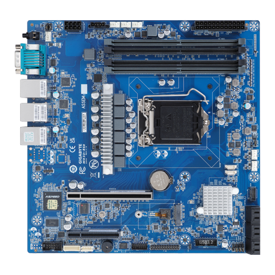
Page 5: Mx33-Bs0 Motherboard Layout
MX33-BS0 Motherboard Layout - 5 -... - Page 6 Item Code Description USB3_MLAN Server Management LAN Port (Top)/USB 3.2 Ports (Bottom) USB2_LAN1 GbE LAN Port #1 (Top)/USB 2.0 Ports (Bottom) USB2_LAN2 GbE LAN Port #2 (Top)/USB 2.0 Ports (Bottom) COM1_VGA_1 Serial Port (Top)/VGA Port (Bottom) SW_ID ID Button with LED SYS_FAN1 System Fan Connector #1 ATX_12V...
-
Page 7: Block Diagram
Block Diagram 2-Channel DDR4 4 x UDIMM slots PCIe4.0 x16 PCIe x16 Rocket Lake PCIe4.0 x4 PCIe x8 LGA1200 (Socket H5) SPI Flash Switch 256MB PCIe3.0 x4 COM2 SATAIII x6 6 x SATA III eSPI COM1 ASPEED USB2.0 x2 USB3.2 Gen1 x2 AST2500 F_USB3.2 Gen1 Intel C252... -
Page 8: Chapter 1 Hardware Installation
Chapter 1 Hardware Installation Installation Precautions The motherboard contains numerous delicate electronic circuits and components which can become damaged as a result of electrostatic discharge (ESD). Prior to installation, carefully read the user's manual and follow these procedures: • Prior to installation, do not remove or break motherboard S/N (Serial Number) sticker or warranty sticker provided by your dealer. -
Page 9: Product Specifications
Product Specifications NOTE: We reserve the right to make any changes to the product specifications and product-related information without prior notice. microATX Š Form Factor 244W x 244D (mm) Š Intel® Xeon® E-2300 series processors Š 11th Gen. Intel Pentium® processors Š... - Page 10 1 x TPM Header with SPI Interface Š Optional TPM2.0 kit: CTM010 Š Board Aspeed® AST2500 Management Controller Š Management GIGABYTE Management Console (AMI MegaRAC SP-X) Web Interface Š Operating Operating temperature: 10°C to 40°C Š Properties Operating humidity: 8-80% (non-condensing) Š...
-
Page 11: Installing And Removing The Cpu
Installing and Removing the CPU Read the following guidelines before you begin to install the CPU: • Make sure that the motherboard supports the CPU. • Always turn off the computer and unplug the power cord from the power outlet before installing the CPU to prevent hardware damage. -
Page 12: Installing And Removing Memory
Installing and Removing Memory Read the following guidelines before you begin to install the memory: • Make sure that the motherboard supports the memory. It is recommended to use memory of the same capacity, brand, speed, and chips. • Always turn off the computer and unplug the power cord from the power outlet before installing the memory to prevent hardware damage. -
Page 13: Installing And Removing A Memory Module
1-4-2 Installing and Removing a Memory Module Before installing a memory module, make sure to turn off the computer and unplug the power cord from the power outlet to prevent damage to the memory module. Be sure to install DDR4 ECC UDIMMs on this motherboard. Follow these instructions to install a UDIMM module: Insert the UDIMM memory module vertically into the UDIMM slot and push it down. -
Page 14: Installing The M.2 Ssd Module
Installing the M.2 SSD Module Follow the steps below to install a M.2 SSD module on your motherboard. Step1. Insert the M.2 SSD module into the slot. Step2. Secure it with the screw, tightening as necessary to fasten the M.2 SSD module in place. Hardware Installation - 14 -... -
Page 15: Back Panel Connectors
Back Panel Connectors ID button with LED When the system identification is active, the ID LED on the front/ back panel glows blue. Serial Port Connects to serial-based mouse or data processing devices. VGA Port Connect to a monitor device. GbE LAN Port #2 The Gigabit Ethernet LAN port provides Internet connection at up to 1 Gbps data rate. See the section below for a description of the states of the LAN port LEDs. -
Page 16: Internal Connectors
Internal Connectors PMBUS ATX_12V 12) F_U32 SATA3_0_1 13) FP_1 SATA3_2_3 14) BP_1 SATA3_4_5 15) COM2 SATA_SGP2/SATA_SGP1 16) TPM CPU_FAN 17) IPMB SYS_FAN1 18) LED_BMC1 SYS_FAN2/3 19) BAT1 10) SYS_FAN4/5 20) CASE_OPEN Read the following guidelines before connecting external devices: • First make sure your devices are compliant with the connectors you wish to connect. •... - Page 17 1/2) ATX/ATX_12V (2x12 Main Power Connector and 2x4 12V Power Connector) With the use of the power connector, the power supply can supply enough stable power to all the components on the motherboard. Before connecting the power connector, first make sure the power supply is turned off and all devices are properly installed. The power connector possesses a foolproof design. Connect the power supply cable to the power connector in the correct orientation.
- Page 18 3/4/5) SATA3_0_1/SATA3_2_3/SATA3_4_5 (SATA III 6Gb/s Connectors) The SATA connectors conform to SATA III 6Gb/s standard and are compatible with SATA 3Gb/s standard. Each SATA connector supports a single SATA device. Pin No. Definition 6) SATA_SGP1/SATA_SGP2 (SATA SGPIO Connector) Serial General Purpose Input/Output (SGPIO) is a communication method used between a host bus adapter (HBA) and a main board.
- Page 19 7/8/9/10) CPU_FAN/SYS_FAN1/SYS_FAN2/SYS_FAN3/SYS_FAN4/SYS_FAN5 (Fan Headers) The motherboard has one 4-pin CPU fan header (CPU_FAN), and two 4-pin (SYS_FAN) system fan headers. Most fan headers possess a foolproof insertion design. When connecting a fan cable, be sure to connect it in the correct orientation (the black connector wire is the ground wire). The motherboard supports CPU fan speed control, which requires the use of a CPU fan with fan speed control design.
- Page 20 12) F_U32 (Front Panel USB 3.2 Connector) The header conform to USB 3.2 specification. Each USB header can provide two USB ports via an optional USB bracket. For purchasing the optional USB bracket, please contact the local dealer. Pin No. Definition Pin No. Definition Power IntA_P2_D+ IntA_P1_SSRX- IntA_P2_D- IntA_P1_SSRX+ IntA_P2_SSTX+ IntA_P1_SSTX- IntA_P2_SSTX- IntA_P1_SSTX+ IntA_P2_SSRX+ IntA_P1_D- IntA_P2_SSRX- IntA_P1_D+ Power No Pin 13) FP_1 (Front Panel Header)
- Page 21 14) BP_1 (HDD Backplane Board Connector) Pin No. Definition Pin No. Definition Reserved BP_SGDIN BP_SGDOUT BP_SGLD BP_SGCLK PLD_Program_EN GLED_AMB_N GLED_GRN_N FAN_IRQ_N Reserved BP_SCL BP_SDA BP_RST_N SMB_U2_TMP_SCL SMB_U2_TMP_SDA 12C_DEV_RST Reserved Reserved Reserved Reserved P3V3_AUX P3V3_AUX 15) COM2 (Serial Port Cable Connector) The COM header can provide one serial port via an optional COM port cable.
- Page 22 16) TPM (Trusted Platform Module Connector) Trusted Platform Module (TPM) is an international standard for a secure cryptoprocessor, a dedicated microcontroller designed to secure hardware through integrated cryptographic keys. 13 14 Pin No. Definition Pin No. Definition SPI_TPM_CLK P_3V3_AUX RST_PLTRST VCC3 SPI_TPM_MISO IRQ_TPM_SPI...
- Page 23 18) LED_BMC1 (BMC Firmware Readiness LED) State Description BMC firmware is initial Blink BMC firmware is ready AC loss 19) BAT1 (Battery Socket) The battery provides power to keep the values (such as BIOS configurations, date, and time information) in the CMOS when the computer is turned off. Replace the battery when the battery voltage drops to a low level, or the CMOS values may not be accurate or may be lost. •...
- Page 24 20) CASE_OPEN (Case Open Intrusion Alert Header) This motherboard provides a chassis detection feature that detects if the chassis cover has been removed. This function requires a chassis with chassis intrusion detection design. Open: Normal Operation (Default) Closed: Active Chassis Intrusion Alert Hardware Installation - 24 -...
-
Page 25: Jumper Settings
Jumper Settings Clear CMOS J_CLRCMOS Default Enable BIOS Recovery BIOS_RCVR Default Enable Password Clear J_PASSWORD Default Enable Force Update ME_UPDATE Default Enable Jumper Name Jumper Setting 1-2: Normal operation (Default) ME Force Update 2-3: Enable ME Force Update 1-2: Normal operation (Default) Password Clear 2-3: Clear administrator and user passwords 1-2: Normal operation (Default) -
Page 26: Chapter 2 Bios Setup
Chapter 2 BIOS Setup BIOS (Basic Input and Output System) records hardware parameters of the system in the EFI on the motherboard. Its major functions include conducting the Power-On Self-Test (POST) during system startup, saving system parameters, loading the operating system etc. The BIOS includes a BIOS Setup program that allows the user to modify basic system configuration settings or to activate certain system features. When the power is turned off, the battery on the motherboard supplies the necessary power to the CMOS to keep the configuration values in the CMOS. - Page 27 Main This setup page includes all the items of the standard compatible BIOS. Advanced This setup page includes all the items of AMI BIOS special enhanced features. (ex: Auto detect fan and temperature status, automatically configure hard disk parameters.) Chipset This setup page includes all the submenu options for configuring the functions of the Platform Controller Hub. Server Management Server additional features enabled/disabled setup menus. ...
-
Page 28: The Main Menu
The Main Menu Once you enter the BIOS Setup program, the Main Menu (as shown below) appears on the screen. Use arrow keys to move among the items and press <Enter> to accept or enter other sub-menu. Main Menu Help The on-screen description of a highlighted setup option is displayed on the bottom line of the Main Menu. - Page 29 Parameter Description Access Level Display the privileges level information. Project Name Displays the project name information. Project Version Displays version number of the BIOS setup utility. Build Date and Time Displays the date and time when the BIOS setup utility was created. BMC Information (Note1) BMC Firmware Version (Note1) Displays BMC firmware version information.
- Page 30 Parameter Description ME Firmware Information ME FW Version Displays the ME firmware version information. Onboard LAN Information LAN1 MAC Address (Note) Displays LAN MAC address information. LAN2 MAC Address (Note) Displays LAN MAC address information. System Date Sets the date following the weekday-month-day-year format. System Time Sets the system time following the hour-minute-second format.
-
Page 31: Advanced Menu
Advanced Menu The Advanced Menu displays submenu options for configuring the function of various hardware components. Select a submenu item, then press <Enter> to access the related submenu screen. BIOS Setup - 31 -... -
Page 32: Cpu Configuration
2-2-1 CPU Configuration Parameter Description CPU Configuration Type/ID/Speed/L1 Data Cache/ L1 Instruction Cache/L2 Cache/ Displays the technical information for the installed processor(s). L3 Cache/CPU Flex Ratio Settings Enable/Disable this item to turn on/off the MLC streamer prefetcher. Hardware Prefetcher Options available: Disabled, Enabled. Default setting is Enabled. When enabled, cache lines are fetched in pairs. - Page 33 Parameter Description Options available: Disabled, Enabled. Default setting is Enabled. MachineCheck Options available: Disabled, Enabled. Default setting is Enabled. MonitorMWait Options available: Disabled, Enabled. Default setting is Enabled. Enables utilization of additional hardware capabilities provided by Intel Trusted Execution Intel(R) Trusted Execution Technology. Changes requires a full power Technology cycle to take effect.
-
Page 34: Power & Performance
2-2-2 Power & Performance Parameter Description Power & Performance CPU-Power Management Press [Enter] to configure advanced items. Control BIOS Setup - 34 -... - Page 35 2-2-2-1 CPU-Power Management Control Parameter Description CPU-Power Management Control Selects the performance state that the BIOS will set starting from reset vector. Boot performance mode Options available: Max Battery, Max Non-Turbo performance, Turbo Performance. Default setting is Turbo Performance. Allows more than two frequency ranges to be supported. Intel(R) SpeedStep(tm) Options available: Disabled, Enabled.
- Page 36 Parameter Description Enable/Disable HwP Fast MSR Support for IA32_HWP_REQUEST HwP Fast MSR Support MSR. Options available: Disabled, Enabled. Default setting is Enabled. When Enabled, it can be enabled by OS if OS native support is HDC Control available. Options available: Disabled, Enabled. Default setting is Enabled. Enable/Disable processor Turbo mode (requires EMTTM enabled).
-
Page 37: Server Me Configuration
2-2-3 Server ME Configuration BIOS Setup - 37 -... - Page 38 Parameter Description General ME Configuration Oper./Backup/Recovery Displays the ME firmware version information. Firmware Version ME Firmware Status 1/2 Displays the ME firmware status 1/2 information. Current State/Error Code/ Displays the ME firmware information of Current State/Error Code/ Recovery Cause Recovery Cause. The altitude of the platform location above the sea level, expressed Altitude in meters. The hex number is decoded as 2's complement signed integer.
-
Page 39: Server Me Debug Configuration
2-2-4 Server ME Debug Configuration Parameter Description Press [Enter] to configure advanced items. ME Initialization Complete Timeout Š – This option defines how long BIOS waits for ME to initialize. Enable HSIO Messaging Š – Options available: Disabled, Enabled. Default setting is Disabled. DRAM Init Done Enable Š – Options available: Disabled, Enabled. Default setting is Enabled. - Page 40 Parameter Description Override ICC Clock Settings Š – ICC Clock Spread Spectrum. » Options available: Disabled, Enabled. Default setting is Enabled. HMRFPO via HECI-3 Š – Options available: Disabled, Enabled. Default setting is Disabled. HMRFPO_LOCK Message Š – Options available: Disabled, Enabled. Default setting is Enabled.
- Page 41 Parameter Description HECI-1/2/3/4 Hide in ME Š – Options available: Off, Hide, Disabled. Default setting is Off. DOI3 Setting for HECI Disable Š – Options available: Disabled, Enabled. Default setting is Disabled. Break RTC Configuration Š – Options available: Disabled, Enabled. Default setting is Disabled.
-
Page 42: System Event Log
2-2-5 System Event Log Parameter Description System Errors (Note) Options available: Disabled, Enabled. Default setting is Disabled. Enable/Disable Whea Driver Support. Whea Driver Support Options available: Disabled, Enabled. Default setting is Disabled. Press [Enter] to configure advanced items. Memory corrected Error enabling Š – Options available: Disabled, Enabled. Default setting is Memory Error Enabling Disabled. -
Page 43: Trusted Computing
2-2-6 Trusted Computing Parameter Description Configuration Enable/Disable BIOS support for security device. OS will not show security device. TCG EFI protocol and INT1A interface will not be Security Device Support available. Options available: Enable, Disable. Default setting is Enable. BIOS Setup - 43 -... -
Page 44: S5 Rtc Wake Settings
2-2-7 S5 RTC Wake Settings Parameter Description Enable/Disable system wake on alarm event. Options available: Disabled, Fixed Time. When Fixed Time is selected, Wake System from S5 system will wake on the hr::min::sec specified. Default setting is Disabled. BIOS Setup - 44 -... -
Page 45: Serial Port Console Redirection
2-2-8 Serial Port Console Redirection Parameter Description Console redirection enables the users to manage the system from a COM Console remote location. Redirection (Note) Options available: Enabled, Disabled. Default setting is Disabled. Press [Enter] to configure advanced items. Please note that this item is configurable when COM Console Redirection is set to Enabled. - Page 46 Parameter Description Parity Š – A parity bit can be sent with the data bits to detect some transmission errors. – Even: parity bit is 0 if the num of 1's in the data bits is even. – Odd: parity bit is 0 if num of 1's in the data bits is odd. –...
- Page 47 Parameter Description Legacy Console Redirection Press [Enter] to configure advanced items. Redirection COM Port Š – Selects a COM port for Legacy serial redirection. – Default setting is COM1. Resolution Š – Selects the number of rows and columns used in Console Redirection for legacy OS support. Legacy Console Redirection –...
- Page 48 Parameter Description Flow Control EMS Š – Flow control can prevent data loss from buffer overflow. When sending data, if the receiving buffers are full, a 'stop' signal can Serial Port for Out-of-Band be sent to stop the data flow. Once the buffers are empty, a 'start' EMS Console Redirection signal can be sent to re-start the flow. Hardware flow control uses Settings(continued) two wires to send start/stop signals. – Options available: None, Hardware RTS/CTS, Software Xon/Xoff. Default setting is None.
-
Page 49: Sio Configuration
2-2-9 SIO Configuration Description Parameter Displays the AMI SIO driver version information. AMI SIO Driver Version Super IO Chip Logical Device(s) Configuration Press [Enter] to configure advanced items. Use This Device Š – When set to Enabled allows you to configure the serial port settings. When set to Disabled, displays no configuration for the serial port. –... -
Page 50: Usb Configuration
2-2-10 USB Configuration Parameter Description USB Configuration USB Devices: Displays the USB devices connected to the system. Enable/Disable the XHCI (USB 3.0) Hand-off support. XHCI Hand-off Options available: Disabled, Enabled. Default setting is Enabled. USB hardware delays and time-outs Select the time-out value for USB Control/Bulk/Interrupt transfers. USB transfer time-out Options available: 1 sec, 5 sec, 10 sec, 20 sec. -
Page 51: Network Stack Configuration
2-2-11 Network Stack Configuration Parameter Description Enable/Disable the UEFI network stack. Network Stack Options available: Enabled, Disabled. Default setting is Enabled. Enable/Disable the Ipv4 PXE feature. Ipv4 PXE Support Options available: Enabled, Disabled. Default setting is Enabled. Enable/Disable the Ipv4 HTTP feature. Ipv4 HTTP Support Options available: Enabled, Disabled. -
Page 52: Csm Configuration
2-2-12 CSM Configuration Parameter Description Compatibility Support Module Configuration CSM Support (Note) Options available: Enabled, Disabled. Default setting is Disabled. Options available: UEFI and Legacy, Legacy only, UEFI only. Default setting Boot option filter is UEFI only. Option ROM execution - Network/Storage/Video/ Options available: Do not launch, UEFI, Legacy. Default setting is UEFI. Other PCI devices (Note) Advanced items prompt when this item is defined. -
Page 53: Nvme Configuration
2-2-13 NVMe Configuration Parameter Description NVMe Configuration Displays the NVMe devices connected to the system. BIOS Setup - 53 -... -
Page 54: Chipset Configuration
2-2-14 Chipset Configuration Parameter Description Defines the power state to resume to after a system shutdown that is due to an interruption in AC power. When set to Last State, the system will return to the active power state prior to shutdown. When set to Restore on AC Power Loss (Note) Power Off, the system remains off after power shutdown. Options available: Last State, Power Off, Power On, Unspecified. The default setting depends on the BMC setting. -
Page 55: M/B Slot
2-2-15 M/B Slot Parameter Description Onboard LAN 1/2 Controller Options available: Enabled, Disabled. Default setting is Disabled. BIOS Setup - 55 -... -
Page 56: Tls Auth Configuration
2-2-16 Tls Auth Configuration Parameter Description Press [Enter] for configuration of advanced items. Enroll Cert Š – Press [Enter] to enroll a certificate • Enroll Cert Using File • Cert GUID Server CA Configuration Input digit character in 1111111-2222-3333-4444-1234567890ab format. – Commit Changes and Exit – Discard Changes and Exit Delete Cert Š Press [Enter] for configuration of advanced items. Client Cert Configuration BIOS Setup - 56 -... -
Page 57: Ram Disk Configuration
2-2-17 RAM Disk Configuration Parameter Description Specifies the type of memory to use from available memory pool in system to create a disk. Disk Memory Type Options available: Boot Service Data, Reserved. Default setting is Boot Service Data. Size (Hex) Š – The valid RAM disk size should be multiples of the RAM disk block Create raw size. -
Page 58: Iscsi Configuration
2-2-18 iSCSI Configuration Parameter Description Press [Enter] configure advanced items. Attempt Priority Š Attempt Priority – Options available: Host Attempt, Redfish Attempt. Default setting is Host Attempt. Commit Changes and Exit Š Press [Enter] to configure advanced items. iSCSI Initiator Name Š – Only IQN format is accepted. Range: from 4 to 223 Host iSCSI Configuration Add an Attempt Š... -
Page 59: Intel(R) I210 Gigabit Network Connection
2-2-19 Intel(R) I210 Gigabit Network Connection BIOS Setup - 59 -... - Page 60 Description Parameter Press [Enter] to configure advanced items. Link Speed Š – Allows for automatic link speed adjustment. – Options available: Auto Negotiated, 10 Mbps Half, 10 Mbps Full, 100 Mbps Half, 100 Mbps Full. Default setting is Auto Negotiated. Wake On LAN NIC Configuration Š – Enables power on of the system via LAN. Note that configuring Wake on LAN in the operating system does not change the value of this setting, but does override the behavior of Wake on LAN in OS controlled power states.
-
Page 61: Vlan Configuration
2-2-20 VLAN Configuration Parameter Description Press [Enter] to configure advanced items. Create new VLAN Š VLAN ID Š – Sets VLAN ID for a new VLAN or an existing VLAN. – Press the <+> / <-> keys to increase or decrease the desired values. – The valid range is from 0 to 4094. Priority Š... -
Page 62: Ipv4 Network Configuration
2-2-21 IPv4 Network Configuration Parameter Description Indicates whether network address is configured successfully or not. Configured Options available: Enabled, Disabled. Default setting is Disabled. Options available: Enabled, Disabled. Default setting is Disabled. Enable DHCP (Note) Local IP Address Press [Enter] to configure local IP address. (Note) Press [Enter] to configure local NetMask. Local NetMask (Note) Press [Enter] to configure local Gateway Local Gateway (Note) Press [Enter] to configure local DNS servers Local DNS Servers (Note) -
Page 63: Mac Ipv6 Network Configuration
2-2-22 MAC IPv6 Network Configuration Parameter Description Press [Enter] to configure advanced items. Displays the MAC Address information. Š Interface ID Š – The 64 bit alternative interface ID for the device. The string is colon separated. e.g. ff:dd:88:66:cc:1:2:3. DAD Transmit Count Š – The number of consecutive Neighbor solicitation messages sent Enter Configuration Menu while performing Duplicate Address Detection on a tentative address. -
Page 64: Driver Health
2-2-23 Driver Health Parameter Description Driver Health Displays driver health status of the devices/controllers if installed. BIOS Setup - 64 -... -
Page 65: Chipset Menu
Chipset Menu Chipset Setup menu displays submenu options for configuring the function of Platform Controller Hub(PCH). Select a submenu item, then press <Enter> to access the related submenu screen. BIOS Setup - 65 -... -
Page 66: System Agent (Sa) Configuration
2-3-1 System Agent (SA) Configuration Parameter Description Press [Enter] to configure advanced items. Memory Š – Press [Enter] to view/configure memory overclocking menu. Memory Configuration Š Memory Frequency Š – Displays the frequency information of installed memory. Memory Configuration Channel and slot information of memory DIMMs. Š Max TOLUD Š – Maximum Value of TOLUD. Dynamic assignment would adjust TOLUD automatically based on largest MMIO length of installed graphic controller –... -
Page 67: Pch-Io Configuration
2-3-2 PCH-IO Configuration Parameter Description PCH-IO Configuration Press [Enter] to configure advanced items. SATA Controller Š – Enable/Disable SATA controller. – Options available: Enabled, Disabled. Default setting is Enabled. SATA Mode Selection Š SATA And RST – Configures on chip SATA type. Configuration – Options available: AHCI, Intel RST Premium with Intel Optane System Acceleration. -
Page 68: Server Management Menu
Server Management Menu Parameter Description Enable/Disable FRB-2 timer (POST timer). FRB-2 Timer Options available: Enabled, Disabled. Default setting is Disabled. Configures the FRB2 Timer timeout. FRB-2 Timer Options available: 3 minutes, 4 minutes, 5 minutes, 6 minutes. Default setting is 6 timeout (Note1) minutes. Configures the FRB2 Timer policy. - Page 69 Parameter Description System Event Log Press [Enter] to configure advanced items. View FRU Press [Enter] to view the FRU information. Information BMC network Press [Enter] to configure advanced items. Configuration IPv6 BMC Network Press [Enter] to configure advanced items. Configuration BIOS Setup - 69 -...
-
Page 70: System Event Log
2-4-1 System Event Log Parameter Description Enabling / Disabling Options Change this item to enable or disable all features of System Event SEL Components Logging during boot. Options available: Enabled, Disabled. Default setting is Enabled. Erasing Settings Choose options for erasing SEL. Erase SEL Options available: No;... -
Page 71: View Fru Information
2-4-2 View FRU Information The FRU page is a simple display page for basic system ID information, as well as System product information. Items on this window are non-configurable. (Note) The model name will vary depends on the product you purchased BIOS Setup - 71 -... -
Page 72: Bmc Network Configuration
2-4-3 BMC Network Configuration Parameter Description BMC network configuration Lan Channel 1 Selects to configure LAN channel parameters statically or dynamically (by BIOS or BMC). Configuration Address source Options available: Unspecified, Static, DynamicBmcDhcp, DynamicBmcNonDhcp. Default setting is Unspecified. Current Configuration Address Display the current configuration information. Source Station IP address Displays IP Address information. Subnet mask Displays Subnet Mask information. Station MAC address Displays the MAC Address information. -
Page 73: Ipv6 Bmc Network Configuration
2-4-4 IPv6 BMC Network Configuration Parameter Description IPv6 BMC network configuration IPv6 BMC Lan Channel 1 Enable/Disable IPv6 BMC LAN channel function. When this item is disabled, the system will not modify any BMC network during BIOS IPv6 BMC Lan Option phase. Options available: Unspecified, Disable, Enable. Default setting is Enable. -
Page 74: Security Menu
Security Menu The Security menu allows you to safeguard and protect the system from unauthorized use by setting up access passwords. There are two types of passwords that you can set: • Administrator Password Entering this password will allow the user to access and change all settings in the Setup Utility. •... -
Page 75: Secure Boot
2-5-1 Secure Boot The Secure Boot submenu is applicable when your device is installed the Windows 8 (or above) operating ® system. Parameter Description System Mode Displays if the system is in User mode or Setup mode. Enable/ Disable the Secure Boot function. Secure Boot Options available: Enabled, Disabled. - Page 76 Parameter Description Press [Enter] to configure advanced items. Please note that this item is configurable when Secure Boot Mode is set to Custom. Factory Key Provision Š – Allows to provision factory default Secure Boot keys when system is in Setup Mode. – Options available: Enabled, Disabled. Default setting is Disabled. Restore Factory Keys Š...
- Page 77 Parameter Description Authorized TimeStamps (DBT) Š – Displays the current status of the Authorized TimeStamps Database. – Press [Enter] to configure a new DBT or load additional DBT from storage devices. Key Management – Options available: Update, Append. (continued) OsRecovery Signatures Š – Displays the current status of the OsRecovery Signature Database. –...
-
Page 78: Boot Menu
Boot Menu The Boot menu allows you to set the drive priority during system boot-up. BIOS setup will display an error message if the legacy drive(s) specified is not bootable. Parameter Description Boot Configuration Number of seconds to wait for setup activation key. 65535 (0xFFFF) Setup Prompt Timeout means indefinite waiting. Press the numeric keys to input the desired values. - Page 79 Parameter Description FIXED BOOT ORDER Priorities Press [Enter] to configure the boot priority. By default, the server searches for boot devices in the following sequence: Hard drive. Boot Option #1 / #2 / #3 / #4 / #5 CD-COM/DVD drive. USB device. Network. UEFI. BIOS Setup - 79 -...
-
Page 80: Save & Exit Menu
Save & Exit Menu The Save & Exit menu displays the various options to quit from the BIOS setup. Highlight any of the exit options then press <Enter>. Parameter Description Save Options Restarts the system after saving the changes made. Save Changes and Reset Options available: Yes, No. -
Page 81: Bios Post Beep Code (Ami Standard)
BIOS POST Beep code (AMI standard) 2-8-1 PEI Beep Codes # of Beeps Description Memory not Installed. Memory was installed twice (InstallPeiMemory routine in PEI Core called twice) Recovery started DXEIPL was not found DXE Core Firmware Volume was not found Recovery failed S3 Resume failed Reset PPI is not available...
Need help?
Do you have a question about the MX33-BS0 and is the answer not in the manual?
Questions and answers