Table of Contents
Advertisement
Quick Links
INSTRUCTION MANUAL
CENTRAL COMMAND
STATION MX10
digital command station
and MX10EC
The Economy
digital command station
EDITIONS:
2013 03 15
2013 10 15
2013 11 23
2014 02 28
2014 04 04
2014 04 05
2014 12 02
2014 12 03
2014 12 10
2014 12 16
2015 02 04
2015 04 10
2015 05 27
2015 07 21
2015 10 20
2015 12 07
2016 02 11
2016 03 14
2016 04 05
SW 01.20.0001 - 2016 09 22
2016 12 10
SW 01.20.0150 - 2017 01 31
2017 05 16
2017 10.12
SW 01.22.0001 - 2017 12 20
2018 05 03
SW 01.24.0001 - 2018 07 30
2018.12.18
2019 05 25
Added: Startset with the Maus - 2019 10 19
Advertisement
Table of Contents

Related Manuals for ZIMO MX10


Summary of Contents for ZIMO MX10
- Page 1 SW 01.22.0001 - 2017 12 20 2018 05 03 SW 01.24.0001 - 2018 07 30 2018.12.18 2019 05 25 Added: Startset with the Maus - 2019 10 19 CENTRAL COMMAND STATION MX10 digital command station and MX10EC The Economy digital command station...
-
Page 2: Table Of Contents
Page 19 - MX10EC Programming Track, Addition MX10EC Emergency Stop Page 23 - MX10EC Section about Normal Screen added 2019 09 01: Occasion: Start of delivery of the "Starset with the maus", MX10 or MX10EC with Roco WLAN Multimaus Pages 9, 10 inserted This instruction manual contains elements which refer to features that are not yet fully implemented. - Page 3 Update & Sound” (“Update - System”). The download is free of charge. General information: • Do not use ZIMO devices in excessively warm or humid locations. The air flow must not be restrict- ed (e.g. by covering) when in operation.
- Page 4 NOT connected to this CAN socket, but to the Select files to up- Broadcast Stop BCS, OFF track 1, track 2, overcurrent OVC (short cir- socket on the rear side of the MX10. 2 sec STOP & OFF date the decoder or...
- Page 5 (S=track) site. to supply stationary equipment modules StEin, track section Regulated DC connection modules, terminal loop modules, and others (within the MX10 DCC power amplifiers). ground 12 and 30 Volts. All necessary connectors are included in the scope of supply.
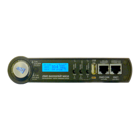
- Page 6 Page6 INSTRUCTION MANUAL CENTRAL COMMAND STATIONS MX10, MX10EC • Display (128 x 32, RGB backlight) USB (Host) socket ZIMO CAN and XNET sockets • Normal screen BLUE Voltages, currents, track 1 / 2, communication statistics, AOS Slot for the flash drive.
- Page 7 3-fold socket “DC out” “ S, GROUND, 12 V (S=track) to supply stationary equipment modules StEin, track section modules, terminal loop modules, and others (within the MX10 DCC power amplifiers). All necessary connectors are included in the scope of supply.
-
Page 8: The First Start-Up Of A Zimo System
The layout with a self-made cable (using the supplied double screw clamp connectors Dou- ble screw clamp “Schiene 1” (track 1) or “Schiene 2” (track 2) of te MX10 or Double screw clamp “Schiene” (track) of the MX10EC. -
Page 9: Power Supply And Technical Data
(adjustable in 1 sec steps) 1 to 60 sec 1 sec ply unit a product from ZIMO or from another manufacturer can be used, as long as it fulfills the - overcurrent threshold (adjustable in 0.1 A steps) 1 to 12 A... -
Page 10: Typical System Arrangement
Page10 INSTRUCTION MANUAL CENTRAL COMMAND STATIONS MX10, MX10EC The WLAN mouse and router included in the ZIMO starter kit are already correctly set to ensure imme- Typical system arrangement diate operation. If there are any problems or the devices were not purchased within a start set, see chapter "Roco Z21 and WLAN mouse“. - Page 11 INSTRUCTION MANUAL CENTRAL COMMAND STATION MX10, MX10EC Page11...
- Page 12 Roco central station Z21, which was used up until now, is replaced by a ZIMO MX10 central station. This is usually the case, if you need MX10’s better perfor- MX10:...
- Page 13 Such an own power supply unit and this circuit should always be used, if more than 5 socket: either by manufacturing the necessary cable yourself or by us- StEin modules (with MX10) or more than 1 StEin module (with MX10EC) are used. ing the "connection and distribution board" MX10AVP (see relevant Only in smaller applications is it advisable to use the accessory voltage for the StEin chapter).
- Page 14 SW July 2018 - SW 01.24 and higher If the “normal” track output of the MX10 (“Schiene 1” (track 1) or “S1” with 12 A traction current) is not enough to supply the layout, frankly, there are two possibilities: interconnecting the two track outputs (“S1”...
- Page 15 (plus rail resistance). This can be guaranteed easily by certain lengths of only one such socket per MX10, you have to use a CAN bus distributor (8-pole) for forwarding to a wires and rails (whereby the sum of both poles is effective): third (...) device.
- Page 16 It is necessary to use both CAN buses, because there is a new, faster protocol between the “new” MX32, MX32FU and the MX10, which the “old” devices are not capable of. As soon as there is one device in the system circuit The “red”...
- Page 17 MX32’s function is not changed, as far as no MX8 and/or MX9 modules are connected additionally to the MX10’s CAN. If this is the case, the MX32 run in the “old” CAN protocol and therefore in the “MX1 Attention: There are differently built radio receivers with the same name and type number - only the operation”...
-
Page 18: The "Connection And Distribution Board" Mx10Avp
“CAN-2”. Jumpers to “CAN-2” while the central command station MX10 itself has two CAN sockets (front and back), this way 5 Set the jumpers on the sockets are available, 4 of them on the MX10AVP. This may be useful despite all devices having two MX10AVP accordingly! CAN sockets (for daisy-chaining). - Page 19 In case old and new generation devices shall work together, two separate CAN buses are used. This is work on “CAN1”. Due to the fact that StEin modules (as well as booster MX10) need timing infor- the same as using MX32 and MX31: mation for the DCC track signal, additionally to the actual CAN data bus, wherefore 8-pole CAN ca- - old controllers (until MX31) and all accessory and track section modules (i.e.
- Page 20 MX10 supplies two Xpress networks, which are combined in one socket (“XNET”); MX10AVP has separated sockets “XNET-1” ad “XNET-2” (between the CAN sockets). - to comfortably controlling (via spring clips) the 16-pole pin connector on the MX10, i.e. 8 inputs (for contact rails, emergency stop keys, etc.) and 8 outputs.
-
Page 21: Rail Connections, Programming Track, Aos In/Out
5 A, at the best of 10 A. and are fully stabilised. The MX10 automatically switches the relay, so that it connects “Schiene 2” to the programming track, The limitations: while a controller (and therefore the connection point “Schiene 2” or “Schiene”) is in operation state - Track 1: 1 - 12 A and SERV PROG. - Page 22 Configuration of the AOS inputs see chapter 8.8, the MX10 menu, menu point AOS in/out Moni- tor+Config. NOTE: in software versions, in which this function of the AOS inputs is not yet available, the wire “Boo UE” on the ZIMO CAN socket can be used for the external emergency stop.
-
Page 23: Track Signal, Feedback, Database
“StEin” modules (stationary equipment modules); but those are not only simple local detectors, but also read global notifications (and forward them to the MX10), because on a big layout, the receiving quality can be much better on a single track section than on the command station’s position. -
Page 24: Mx10 Update, Data Import And Storage
MX10 update, data import and storage The MX10 software update is done during operation. If a flash drive with the usable files is connected, all outputs on the MX10 are switched off. All devices which are supplied by the MX10 are therefore The current software version: without current. -
Page 25: Usage And Operating Elements
(Flash drive) sent command packets per sec); of all 14 connections. Insert flash drive (with the files to update the MX10 and/or the decoder software or to load xx DCC = only DCC packets sound into the root directory) screen... - Page 26 “running voltage” and ”OVC the individual needs. threshold” in the “detailed setting” (see description be- low). This display can also be reached via the MX10 Each of the values is displayed and has to be adjusted Current threshold OVC menu (chapter 8.8).
- Page 27 1: (Track 1) and 2: (Track 2) in normal operation: No: the MX10 starts operation on track 1 with the last used (driving) configurations. Yes: the MX10 starts operation on track 1 after the stopping state is confirmed on the controller Running voltage...
- Page 28 Means: if track 1 is ON, it is set to (Broadcast Stop) BCSe when entering into the stopping operation. shown on their displays and and on the MX10’s display. Cancelling broadcast stop started by the rotary knob; going back to normal screen: Button 1...
- Page 29 “OFF”) (except the text “OVC” is a defect in the current limiting circuit. or “UND”) from the MX10 or the controller. Therefore, also the procedure to re-start, etc. is the same: Voltage error on track 1 / track 2 screen colour changes to RED, STOPP &...
- Page 30 Page30 INSTRUCTION MANUAL CENTRAL COMMAND STATIONS MX10, MX10EC Fahrzeugadresse markieren (Drehen, Drücken) BaseCab LOCO (driving op. via central command station) FAHR THIS FUNCTION IS NOT YET IMPLEMENTED - THIS IS A DESCRIPTION OF THE PROJECT Starting point is the normal screen...
- Page 31 Press rotary knob program adjusted value into decoder; open next line BaseCab SERV PROG (programming CVs) If programming was successful (acknowledged by RailCom feedback) the MX10 displays: „ACK RC“ THIS FUNCTION IS NOT YET IMPLEMENTED - THIS IS A DESCRIPTION OF THE PROJECT...
- Page 32 GREY ON … etc. NOTE: The same “BCS & OFF” screen is reached as well via the menu point of the MX10 as via the NOTE: Some of the menu points are not yet working with the commands broadcast stop or track-off by a MX32, or “STOPP” via long pressing the rotary knob on current software version.
- Page 33 “Boo UE” input of the booster socket Celsius at the voltage and current values shown beneath. (MX10 back ZIMO CAN). Options: “BCS S1”, “BCS S2”; “BCS S1+S2”; “OFF S1”; “OFF S2”; “OFF “Peak power” shows the highest voltage and current on each S1+ S2”...
- Page 34 Calling up the decoder SW updates from the menu means that a SW update collection file or sound This function is shown in parentheses on the MX10 and is project previously stored in the MX10’s “file storage” shall be used; the available files are listed. In con- therefore not implemented. You cannot call up the screen...
- Page 35 Press rotary knob opens submenu ACK current: Set to 60 mA corresponding to the NMRA standard. For ZIMO decoders a current of 20 mA is usually Submenu Inp. 1-8: sufficient. A smaller ACK current is needed, if small sensi- You can adjust the thresholds for up and down as well as ble motors are used, e.g.
- Page 36 Display 3: DCC-packet monitor function Shows in intervals of about 0.5 seconds, what kind of NOTE: Driving operation is also possible without looking at the Object Database. In the ZIMO system, packets were sent during this period for this address. The almost any number of addresses can be managed at the same time;...
- Page 37 (most of the time deleting whole address contingents) from the object database Button (): Address DCC packets / sec RailCom feedback / sec track format of the MX10, or of the whole system. Regarding the following steps within the menu point “”ObjectDB Button () Address feedback (via RailCom) speed (km/h) etc.
- Page 38 ObjectDB Sound projects GREY Lists of the sound samples stored in the MX10 (to play back via the “virtual address MX10 Sound”), software decoder collection file and sound projects for decoders (applicable via menu points “ZIMO decoder SW-Update” and “ZIMO decoder sound loading”) ...
- Page 39 Display colour changes to TURQUOISE, list of files Sammelfilexyz.zsu stored on the flash drive is shown (first Sammelfilexyz.zsu ► Sammelfile1234.zsu if necessary an update for the MX10, then the files for ► Sammelfile1234.zsu the decoder). Soundprojektabc.zpp Soundprojektabc.zpp Select desired file (and thereby also action) per rotary knob.
-
Page 40: Roco Z21" App And Other Apps On The Mx10
Opening the (previously installed) app starts it. In “App settings” the IP address has to be entered. For the ZIMO central command station, the IP address by default is (as long as it is not changed in the MX10 menu): 192.168.1.145... -
Page 41: Interlocking Program "Estwgj" On The Mx10
The PC / Laptop has to have a static IP address corresponding to the principles described below. In case of a firewall, it has to be ensured that the MX10 sends data via the UDP ports 14520 (PC sends) and 14521 (PC receives commands; these ports are configured by default in the MX10 and can be changed in the MX10 menu under “PC Config+Monitor”... - Page 42 ESTWGJ the connection works. As described here for ESTWGJ, other interlocking programs can be connected to the MX10. NOTE: MX10 can not communicate via LAN and USB at the same time. As soon as the MX10 recognises a valid LAN connection, USB is deactivated.
-
Page 43: Usb Connection To The Computer
This is a general description, valid for different applications, but NOT a certain program. and activate “load VPC”. For the PC to communicate with an MX10 via USB, they have to be interconnected by a cable type “A if this tab is not available, to mini B”. -
Page 44: Annex: Emv Audit Report / Tüv Austria
Concerning the MX10 command station and MX32 controller. Declaration of Conformity: ZIMO Elektronik GmbH hereby declares that the product MX10 bears the EC mark and is built in ac- cordance with the provisions of Directives 88/378 / EEC; 89/336 / EEC; 73/23 / EEC.
Need help?
Do you have a question about the MX10 and is the answer not in the manual?
Questions and answers