Table of Contents
Advertisement
Large-scale Decoder & Sound Decoder MX695, MX696, MX697, MX699
Instruction Manual
LARGE-SCALE DECODER WITH & W/O SOUND
and NON-SOUND LARGE-SCALE DECODER
and: Combinations of loco boards and decoder
and NON-SOUND LARGE-SCALE DECODER
MX695KV, -KS, -LV, LS
MX695KN
MX696V, -S
MX696KS, MX696KV
MX696KN
MX697V, -S
MX699KV, -KS, -LV, -LM
SW-Version 31 --- 2012 08 15
Including the new MX696 decoder --- 2012 11 30
SW-Version 33.0 --- 2013 04 30
with chapter about loco boards --- 2013 05 20
1
Product - Overview .................................................................................................. 2
2
Technical Information ............................................................................................... 4
3
Installation and Wiring ............................................................................................. 5
4
Loco Adapter Boards for Large-Scale Decoder ...................................................... 12
5
Configuration ........................................................................................................ 18
Programming in "Service mode" (on the progr. track) ............................................................. 18
5.1
Programming in "Operations mode" (on-the-main) .................................................................. 18
5.2
5.3
Decoder-ID, Load-Code, Decoder-Type and SW-Version ...................................................... 19
5.4
Engine address(es) in DCC mode ........................................................................................... 19
5.5
Analog operation ...................................................................................................................... 20
5.6
Motor control and regulation .................................................................................................... 21
5.7
Acceleration and Deceleration: ................................................................................................ 24
5.8
The ZIMO "signal controlled speed influence" (HLU) .............................................................. 26
5.9
"Asymmetrical DCC-Signal" stops (Lenz ABC)........................................................................ 26
5.10
5.11
DC Brake Sections (Märklin brake mode) ............................................................................... 27
5.12
Distance Controlled Stopping - Constant Stopping Distance ................................................. 27
5.13
Shunting, Half-Speed and MAN Functions .............................................................................. 28
5.14
The NMRA-DCC function mapping .......................................................................................... 29
5.15
The extended ZIMO Function mapping ................................................................................... 30
"Unilateral Light Suppression" .................................................................................................. 31
5.16
The "Swiss Mapping" (from SW version 32) ............................................................................ 32
5.17
The ZIMO "Input-Mapping" SW versions 34 and up, also for outputs via SUSI ...................... 34
5.18
5.19
Dimming, Low beam and Direction Bits ................................................................................... 34
5.20
Flasher Effect ........................................................................................................................... 35
5.21
F1-Pulse Chains (Only for old LGB products) ......................................................................... 35
5.22
Special Effects (US and other light effects, smoke generator, uncouplers etc.) ..................... 36
5.23
Configuration of smoke generators .......................................................................................... 37
5.24
Configuration of Electric Uncouplers........................................................................................ 38
5.25
Servo Configuration ................................................................................................................. 40
Feedback - Bidirectional communication ............................................................... 41
6
ZIMO SOUND - Selection and Programming ......................................................... 42
7
7.1
7.2
The test run for determining the motor's basic load ................................................................ 46
7.3
7.4
Basic settings independent of powertrain ................................................................................ 47
Steam engine Basic sound settings .................................................................................... 49
7.5
Steam engine Load and acceleration dependency ............................................................. 51
7.6
7.7
Diesel and Electric engines ..................................................................................................... 53
7.8
Random and Switch input sounds ........................................................................................... 56
CV - Summery List ................................................................................................ 57
8
9
Service Insructions................................................................................................. 60
ZIMO decoders contain a microprocessor with appropriate software. The software version can be read out from CV #7 and #65.
The current version may not yet capable of all the functions mentioned in this manual. As with other computer programs, it is also
not possible for the manufacturer to thoroughly test this software with all the possible applications. Installing new software ver-
sions later can add new functions or correct recognized errors. SW updates can be done by the end user for all ZIMO decoders
since production date October 2004, see chapter "Software Update"! Software updates are available at no charge if performed by
the end user (except for the purchase of a programming module); Updates and/or upgrades performed by ZIMO are not consid-
ered a warranty issue and are at the expense of the customer. The warranty covers hardware damage exclusively, provided such
damage is not caused by the user or other equipment connected to the decoder. For update versions, see www.zimo.at.
Page 1
EDITION
2015 06 01
2011 05 01
2015 07 07
2011 08 15
2015 09 23
2018 04 20
2019 05 16
2014 10 12
Advertisement
Table of Contents

Related Manuals for ZIMO MX699


Summarization of Contents
Product Overview
MX695K Series with Screw Terminals
Details MX695K versions with screw terminals, full and reduced.
MX695KN Non-Sound Decoder with Screw Terminals
Details MX695KN non-sound decoder with screw terminals.
MX695L Series with Pin Connectors
Details MX695L versions with pin connectors, full and reduced.
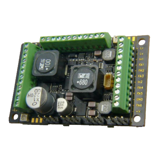
MX696 Series: Narrow Body Decoders
Details MX696V and MX696S narrow body decoders, full and reduced.
MX696N Non-Sound Decoder with Screw Terminals
Details MX696N non-sound decoder with screw terminals.
MX696K Series: Narrow Large-Scale Sound Decoder
MX696KV Full Version
Full version of narrow large-scale sound decoder with screw terminals.
MX696KS Reduced Version
Reduced version of narrow large-scale sound decoder with screw terminals.
MX699K Series: Large-Scale Sound Decoder with Screw Terminals
MX699KV Full Version
Full version of large-scale sound decoder with screw terminals.
MX699KS Reduced Version
Reduced version of large-scale sound decoder with screw terminals.
MX697 Series: Large-Scale Sound Decoder for US Interfaces
MX697V Full Version
Full version of large-scale sound decoder for US interfaces.
MX697S Reduced Version
Reduced version of large-scale sound decoder for US interfaces.
MX699L Series: Large-Scale Sound Decoder with Pin Connectors
MX699LV, -LM Full Version
Full version of large-scale sound decoder with pin connectors.
MX699LS Reduced Version
Reduced version of large-scale sound decoder with pin connectors.
Technical Information
Track Voltage Specifications
Specifies track voltage range for DCC and analog operation.
Motor Output and Peak Current
Details maximum continuous motor output and peak current.
Function Output Current and Outputs
Lists function output current and number of outputs per model.
Sound Sample Capacity and Playback
Capacity for sound samples and playback frequencies.
Sound Amplifier and Loudspeaker Impedance
Sound amplifier output power and loudspeaker requirements.
External Energy Storage Options
Options for external energy storage connection and charge current.
Analog Mode Operation
Information on analog mode operation and threshold voltages.
Operating Temperature and Dimensions
Operating temperature range and physical dimensions of decoders.
Overload and Thermal Protection
Details overload protection mechanisms and thermal protection.
Software Update Information
Information on user-completable software updates for decoders.
Installation and Wiring of MX695 - MX699
Function Output Voltage Options
Describes full track, +10V, +5V, and variable low-voltage for outputs.
External Energy Source Connections
Options for external energy sources like capacitors or batteries.
Special Fan Connection
Connection point for the special fan output.
Rail and Motor Connections
Connections for left/right rails and motor terminals.
Switch Input and Volume Control
Input for switch signals and volume control potentiometer.
Speaker and Cam Sensor Connections
Speaker connection options and cam sensor input.
Servo and SUSI Interface Connections
Connections for up to four servos and SUSI interface.
MX696 Series Wiring Diagram
Function Outputs
Function outputs for various elements on the MX696.
Headlight Connections
Connection points for rear and front headlights.
Rail and Motor Connections
Connections for rails and motor terminals.
Cable and Plug Connections
Connections via ribbon cable and specific plugs for MX696S/V.
SUSI Interface
SUSI interface connection details.
Smoke Fan and Capacitor Connections
Connections for smoke fan motor and external capacitor.
Low-Voltage Settings and Servo Connections
Setting low voltage for servos and servo connections.
MX697 Series Wiring Diagram
Additional Input Switches
Connections for additional input switches.
Headlight and Rail Connections
Front/rear headlight and rail connections.
Motor and Ground Connections
Motor and ground connection points.
Loudspeaker and Capacitor Connections
Loudspeaker and external capacitor connections.
Switch Input and Low-Voltage Regulator
Switch input connections and low-voltage regulator.
Low Voltage Outputs
Low voltage outputs for functions (10V, variable, 5V).
Function Outputs
Function outputs for various elements.
Smoke Fan and Volume Control
Smoke fan motor connection and volume control.
Servo Connections
Connections for up to four servos.
MX699 Series Wiring Diagram
Function Output Voltage Options
Full track, +10V, +5V, and adjustable low-voltage for outputs.
External Capacitor Options
Options for external capacitors.
Fan and Smoke Fan Connections
Fan connections and smoke fan motor connection.
Rail and Motor Connections
Connections for rails and motor terminals.
Switch Input and Speaker Volume
Switch input connection and speaker volume control.
Speaker and Cam Sensor Connections
Speaker connection options and cam sensor input.
Servo and SUSI Interface Connections
Servo and SUSI interface connections.
Additional Switch Connections
Additional switch connections.
Tracks and Motor Connections
Decoder Installation Space Requirement
Requirement for adequate space inside the locomotive for decoder installation.
Insulation of Wiring
Ensuring insulation of wiring for accessories and motor.
Connecting Tracks and Motor to Terminals
Connecting tracks and motor to the corresponding decoder terminals.
DC Motor Compatibility
Compatibility with all DC motors used in model railways.
Parallel Connection for Multiple Motors
Connecting multiple motors in parallel for automatic alignment.
Reference to Motor Regulation CVs
Reference to CVs for motor regulation configuration.
Dual Connection Pins for Tracks and Motor
Availability of dual connection pins for tracks and motor.
Speaker, Cam Sensor, and Volume Regulation
Speaker Compatibility and Impedance
Compatibility of 4 Ohm or 8 Ohm speakers and impedance limits.
Sound Amplifier Power
Sound amplifier power specification for MX699.
Connecting Tweeters
Connecting tweeters in parallel with a frequency crossover.
Volume Adjustment for Low-Specification Speakers
Adjusting volume for speakers with lower specifications.
Virtual Cam Sensor Functionality
Explanation of the sufficiency of the virtual cam sensor.
Connecting Real Cam Sensors
Connecting real cam sensors, mechanical or photo-transistor types.
External Volume Control Options
Alternative volume control via external regulator.
MX695 Specific Volume Regulator Settings
MX695 specific volume regulator settings, logarithmic potentiometer.
Volume Regulator Note for MX696/697/699
Note on volume regulators for MX696, MX697, and MX699 decoders.
Consumers and Low Voltage Outputs
Definition of Consumers
Equipment connected to function outputs (lights, LEDs, motors, etc.).
Using Full Track Voltage as Positive Pole
Using full track voltage as the positive pole for consumers.
Using 10V Low Voltage Output
Using 10V low voltage for sound, with warnings about consumption.
Using 5V Low Voltage Output
Using 5V low voltage for servos and consumers.
Variable Low Voltage Adjustment
Adjusting variable low-voltage via coding switch.
Warning: Avoid Software Dimming for Voltage Reduction
Avoid software dimming for voltage reduction to prevent damage.
Reference to Decoder Configuration CVs
Reference to CV chapters for function mapping and effects.
Special Connections for Smoke Fans
Smoke Generator Fan Control
Using outputs to control fan motors of clocked smoke generators.
Motor Braking Feature for Smoke Fans
Feature allowing motor braking for smoke fans.
Servo Configuration
MX699 Servo Connections
MX699 provides 4 connections for common servos.
Servo Wire Color and Order Differences
Attention to different wire orders and colors for servos.
5V Servo Supply Availability
5V servo supply is only available in V-types.
Servo Control Wires and External Power
Control wires usability and external 5V power source.
Switch Inputs
Additional Switch Inputs
Three further inputs (IN 1, IN 2, IN 4) for triggering sounds etc.
Reference to CVs for Sound Configuration
Reference to CV chapters for sound configuration.
External Stay-Alive Capacitor
Types of Stay-Alive Capacitors
Electrolytic capacitor, Goldcap, or battery types.
Benefits of Stay-Alive Capacitors
Improves driving, reduces flickering lights, prevents stalling.
GOLMRUND Goldcap Module Example
Example of a Goldcap module (GOLMRUND).
MX699 Internal Stay-Alive Capacitor
MX699 Internal Stay-Alive Capacitor Details
MX699 has an internal stay-alive capacitor for passing sections.
Using External Stay-Alive Capacitors with MX699
Benefit of connecting external stay-alive capacitors to MX699.
SUSI Interface
SUSI Interface Purpose and Module Connections
SUSI interface for additional modules like sound or couplers.
SUSI for Digital Couplers and Pantographs
SUSI interface used for digital couplers and pantographs.
SUSI for Sound Project Loading
SUSI interface for loading sound projects and updates.
Loco Adapter Boards Overview
Purpose of Loco Adapter Boards
Adapter boards as intermediate parts for decoder installation.
Note on Synchronous Rectifier Absence
Adapter boards for ZIMO decoders lack additional synchronous rectifiers.
LOKPL95BS/BV Boards for MX695LS/LV
LOKPL95BS/BV boards designed for MX695LS/LV decoders.
LOKPL96 Series Loco Boards
Loco boards designed for MX696S/V decoders.
LOKPL95BS and LOKPL95BV Board Details
LOKPL95BS: Circuit Board with Solder Pads
LOKPL95BS circuit board with solder pads for connections.
LOKPL95BV: Board with Additional Variable Low Voltage
LOKPL95BV features additional variable low voltage output.
Servo Connections on MX695 Decoder
Note: Servo connections are not accessible on the loco board.
Special Loco Board Layouts
Special board layouts may include servo connectors.
LOKPL96 Series Board Variations
LOKPL96KS: Screw Terminals and 5V Low Voltage
LOKPL96KS features screw terminals and 5V low voltage.
LOKPL96KV: Screw Terminals, 5V Low Voltage, Servo Connections
LOKPL96KV features 5V low voltage, servo connections, and screw terminals.
LOKPL96LS: 10-Pin Plugs
LOKPL96LS features 10-pin plugs.
LOKPL96LV: 10-Pin Plugs and 5V Low Voltage
LOKPL96LV features 10-pin plugs and 5V low voltage.
LOKPL96LS/LV Connection Method
Connecting 10-pin plugs using cable and crimp sockets.
Loco Board and Decoder Combinations
MX696KS Combination (LOKPL96KS + MX696S)
MX696KS combination, similar to MX695KS but narrower.
MX696KV Combination (LOKPL96KV + MX696V)
MX696KV combination, similar to MX695KV but narrower.
Loco Board and Sound Decoder Combinations
Combinations with 8 Function Outputs
Various combinations featuring 8 function outputs.
Combinations with 8 Outputs, 5V Low Voltage, and Servos
Combinations with 8 outputs, 5V low voltage, and servo connections.
Combinations with 14 Function Outputs
Various combinations featuring 14 function outputs.
Combinations with 14 Outputs, 5V Low Voltage, and Servos
Combinations with 14 outputs, 5V low voltage, and servo connections.
Combinations with Variable Low Voltage
Combinations featuring variable low-voltage (1.5V to 18V).
Decoder and Loco Board Combinations: Plug-in Sockets
Plug-in Sockets for Ribbon Cable (Narrow Design)
MX696S/V with LOKPL96LS/LV using plug-in sockets.
Double Row Sockets for Ribbon Cable (Narrow Design)
MX696S/V with LOKPL96LV using double row sockets.
Decoder and Loco Board Combinations: Wide Design
MX695KS Decoder without Loco Board
MX695KS decoder without a loco board (wide design).
MX695KV Decoder without Loco Board
MX695KV decoder without a loco board (wide design).
Decoder and Loco Board Combinations: Screw Terminals
MX696S with LOKPL96KS
MX696S with LOKPL96KS using screw terminals.
MX696V with LOKPL96KS
MX696V with LOKPL96KS using screw terminals.
MX696S with LOKPL96KV
MX696S with LOKPL96KV using screw terminals.
MX696V with LOKPL96KV
MX696V with LOKPL96KV using screw terminals.
Attention: 5V Servo Supply
5V Servo Supply Availability Note
Attention: 5V for servos is only available at the variable low-voltage output.
Special Loco Board LOKPLSHMAL
LOKPLSHMAL for MX696S or MX696V
Special board for MX696S or MX696V, for HSB Mallet 995901.
Loco Conversion Notes (HSB Mallet Example)
Notes on loco conversion using the HSB Mallet example.
ZIMO Board Connection for Energy Storage
ZIMO board offers connection for energy storage device.
Additional Connections for Uncouplers
Additional connections for uncouplers (servos or Massoth).
Analog Version Loco Conversion
Procedure for converting analog version locomotives.
HSB Mallet Decoder Sound Project Details
Details of the HSB Mallet decoder's high-quality sound project.
Connection Diagram for LOKPLSHMAL
Connection diagram for the LOKPLSHMAL loco board.
LOKPL99 Loco Board with Solder Pads
LOKPL99 for MX699LS and MX699LV
LOKPL99 board with solder pads for MX699LS and MX699LV.
Installation of LOKPL99 Boards
Instructions for installing LOKPL99 boards with wires soldered.
Connection Diagram for LOKPL99
Connection diagram for the LOKPL99 loco board.
Servo Connection Note for MX695
Note: Servos connect directly to the MX695 decoder.
Configuring the MX695 - MX699
Programming Modes: Service vs. Operations
Explains programming in Service Mode and Operations Mode (PoM).
Note on Default CV Values for Sound Decoders
CV values in sound decoders may differ from defaults.
Common CV Adjustments in Sound Projects
Highlights common CV adjustments in sound projects (e.g., CV #29).
Service Mode Programming
Unlocking Service Mode with CV #144
Unlocking Service Mode programming using CV #144.
Acknowledgement Methods in Service Mode
Methods for acknowledging successful programming steps.
Alternative Acknowledgement Method (CV #112)
Using CV #112 for alternative acknowledgement signals.
Operations Mode Programming
Explanation of Operations Mode (PoM)
Explanation of Operations Mode programming (Programming-on-the-main).
DCC Standards for Operations Mode
DCC standards for programming and reading CVs on the main track.
ZIMO Decoders and RailCom for PoM
ZIMO decoders use RailCom for PoM operations.
RailCom Activation Settings
Settings required to activate RailCom for PoM.
Decoder Identification and Version Information
Decoder ID and Type (CV #250)
Decoder ID and type information stored in CV #250.
Load-Code for Coded Sound Projects
Load-code for installing coded sound projects.
Manufacturer ID and Reset Functions (CV #8)
Manufacturer ID and Reset functions via CV #8.
Software Version Number (CV #7)
Decoder SW version number indicated by CV #7.
Sub-Version Number (CV #65)
Sub-version number indicated by CV #65.
Engine Addressing in DCC Mode
Default Engine Address and Recommendations
Default address (CV #1) and recommendations for changing it.
DCC Address Space and Long Addresses
DCC address space exceeding single CV, long addresses.
Automatic Address Calculation by Digital Systems
How digital systems calculate addresses automatically.
Decoder-Controlled Consisting
Consisting via DCC System
Organizing consisting using the DCC system without CV changes.
Consisting via Individual CV Programming
Organizing consisting by programming decoder CVs individually.
Focus on Decoder-Controlled Consisting
This chapter covers only decoder-controlled consisting.
Analog Operation
Analog Operation Capabilities (DC/AC)
All ZIMO decoders operate in DC or AC analog modes.
Enabling Analog Operation via CV #29
Enabling analog operation by setting CV #29, Bit 2 = 1.
Analog Operation Design for Large-Scale Decoders
Large-scale decoders designed for analog operation.
Controller Influence on Analog Behavior
Influence of locomotive controller on analog operation.
Motor Control and Regulation
Note on Default CV Values vs. Sound Projects
Note that decoder settings may differ from defaults due to sound projects.
Speed Curve Programming
Information on programming the speed curve.
Three-Step Speed Curve Programming
Programming three-step speed curves using CVs #2, #5, #6.
28-Step Speed Curve Programming
Free programmable speed curve using CVs #67 - #94.
CV #57: Motor Control Reference Voltage
CV #57 specifies the reference voltage for motor regulation.
Fine-Tuning Motor Regulation
Tips for Optimizing CV #56 Settings
Steps for finding optimal CV #56 settings for motor regulation.
CV #9: Motor Control Frequency and EMF Sampling
CV #9 for adjusting motor control frequency and EMF sampling rate.
CV #56: PID Regulation Parameters
CV #56 for tailoring motor regulation with PID values.
Motor Control Frequency and EMF Sampling Rate (CV #9)
Motor Control via Pulse Width Modulation
Motor control using pulse width modulation at different frequencies.
Low Frequency Motor Control
Use of low frequency motor control (30-159Hz) for older motors.
High Frequency Motor Control
Use of high frequency motor control (20kHz) for quiet operation.
Periodic Motor Power Interruption
Periodic interruption for EMF measurement and load compensation.
Adjusting Sampling Frequency with CV #9
Adjusting sampling frequency and time using CV #9.
PID Regulation (CV #56)
Tailoring Motor Regulation with PID Values
Tailoring motor regulation to type, weight using PID values.
Setting PID Values with CV #56
Setting proportional and integral values using CV #56.
Fine-Tuning Suggestions for Default Settings
CV #9 and CV #56 Remarks for Fine-Tuning
Remarks on CVs #9 and #56 for fine-tuning motor regulation.
Procedure for Optimal CV #56 Settings
Steps for finding optimal CV #56 settings.
Load Compensation, Curve, and Experimental CVs
Goal of Load Compensation
Objective of load compensation: maintaining constant speed.
Using 100% Load Compensation
Usefulness of 100% load compensation for preventing stalls.
Warning: Load Compensation in Consists
Warning against 100% load compensation in consists.
Defining Load Compensation Intensity (CV #58)
Defining load compensation intensity using CV #58.
Advanced Load Compensation (CVs #10, #113)
Using CVs #10 and #113 for precise load compensation.
Experimental CVs for Test Purposes
Experimental CVs for testing effects on motor regulation.
CV #58: BEMF Intensity
CV #58 for adjusting BEMF intensity.
CV #10: EMF Feedback Cutoff
CV #10 for controlling EMF feedback cutoff.
CV #113: BEMF Reduction
CV #113 for reducing BEMF intensity.
The Motor Brake
Purpose of the Motor Brake
Usefulness of the motor brake for preventing roll-away on inclines.
CV #151: Motor Brake Control
CV #151 for controlling the motor brake.
Acceleration and Deceleration Settings
Basic Acceleration and Deceleration Times (CVs #3, #4)
Setting basic acceleration and deceleration times with CVs #3 and #4.
NMRA Standard for Acceleration/Deceleration
NMRA standard requires a linear progression for acceleration/deceleration.
Recommended Values for Smooth Driving
Recommended values for smooth drivability and slow starts/stops.
Sound Project Default Values for CVs #3, #4
Sound projects may have different default values for CVs #3 and #4.
Improving Acceleration/Deceleration with CVs #121, #122, #123
Enhancing acceleration/deceleration using exponential and adaptive features.
CV #146: Eliminating Start-Up Jolts
CV #146 for eliminating start-up jolts caused by gear backlash.
Special Operating Mode: km/h Speed Regulation
Introduction to km/h Speed Regulation
Alternative method for driving with prototypical speeds using km/h.
Calibration Run Requirement
Calibration run must be performed for each engine.
Calibration Step 1: Engine Setup
Initial engine setup for the calibration run.
Calibration Step 2: Starting Calibration Mode (CV #135)
Starting calibration mode by programming CV #135.
Calibration Step 3: Setting Speed Regulator
Setting the speed regulator to a medium speed position.
Calibration Step 4: Function Activation
Activating function F0 (headlights) at the start marker.
Calibration Step 5: Reading CV #136
Reading CV #136 for calibration results.
CV #135: Normal vs. km/h Operation Control
CV #135 controls selection between normal or km/h operation.
Signal Controlled Speed Influence (HLU)
Introduction to ZIMO Signal Controlled Speed Influence (HLU)
HLU offers a second level of communication for track section data.
HLU Application: Train Stopping and Speed Limits
HLU used for stopping trains and applying speed limits in stages.
HLU Acceleration/Deceleration Time Note
Note on HLU acceleration/deceleration times (CVs #49, #50).
Importance of Track Layout for HLU
Proper track layout is crucial for functioning HLU train control.
Importance of Stop/Pre-Braking Sections for HLU
Correct stop/pre-braking sections are vital for HLU train control.
CV #49: HLU Acceleration
CV #49 for configuring HLU acceleration.
CV #50: HLU Deceleration
CV #50 for configuring HLU deceleration.
HLU Method with MX9 or Successor
HLU method using MX9 track section modules or successors.
Defining HLU Speed Limits
Defining internal speed steps for HLU speed limits.
CVs #51-55: HLU Speed Limits
CVs #51 through #55 for setting HLU speed limits.
CV #59: HLU Reaction Time
CV #59 for configuring HLU reaction time.
Asymmetrical DCC Signal Stops (Lenz ABC Method)
Activating Asymmetrical DCC Signal Stop Mode (CV #27)
Activating the asymmetrical DCC signal stop mode using CV #27.
Note on ABC Slow Speed Step Support
Note: ZIMO decoders do not support standard ABC slow speed steps.
Position Dependent Stops with ABC Method
Position dependent stops using the Lenz ABC method.
Asymmetrical Threshold Adjustment for ABC Stops
Adjusting the asymmetrical threshold for ABC stops.
CV #142: High-Speed Correction for ABC Stops
CV #142 for high-speed correction in ABC asymmetrical stops.
DC Brake Sections (Märklin Brake Mode)
Classic Automated Control Methods
Classic methods for automated layout control or stopping at signals.
Settings for Track-Polarity Dependent DC Brake Sections
Settings for track-polarity dependent DC brake sections.
Settings for Polarity Independent DC Brake Sections
Settings for polarity independent DC brake sections (Märklin).
Distance Controlled Stopping
Selecting Constant Stopping Method (CV #140)
Selecting constant stopping method using CV #140.
Suitability for Red Signals and HLU/ABC
Method suitability for red signals and HLU/ABC influences.
Distance Controlled Stopping for Manual Driving
Distance controlled stopping activation for manual driving.
CV #141: Setting Constant Stopping Distance
CV #141 for setting the constant stopping distance.
CV #142: High-Speed Compensation for HLU
CV #142 for high-speed compensation with HLU.
Shunting, Half-Speed, and MAN Functions
Prototypical Acceleration/Deceleration (CVs #3, #4, #121-123)
Prototypical acceleration/deceleration using various CVs.
Temporarily Reducing Momentum with Function Keys
Temporarily reducing or eliminating momentum with function keys.
CV #124: Shunting Key Functions Summary
CV #124 summarizes shunting key functions.
Preferred CVs for Shunting/MAN Functions
CVs #155, #156, #157 are preferred for shunting/MAN functions.
Shunting Key Functions: Low Gear and Momentum
Shunting key functions for low gear activation and momentum.
NMRA-DCC Function Mapping
Function Outputs (FO) Overview
ZIMO decoders have 8 or 14 function outputs (FO).
Controlling Loads via Function Keys
Controlling loads (lights, smoke generators) using function keys.
Limitations of NMRA Function Mapping
Limitations include 8-Bit register and directional headlights.
CVs #33 to #46 for NMRA Function Mapping
CVs #33 to #46 for specifying NMRA function mapping.
Modified NMRA Function Mapping
Example of Function Mapping Modification
Example showing modification of function mapping.
CV #61 for Alternative Function Mapping
CV #61 offers alternative function mapping without left shifts.
Direction Dependent Taillights with Special Effect CVs
Using special effect CVs for direction dependent taillights.
Example 1: Red Taillights Switched with F1
Example 1: Red taillights switched with F1, changing direction.
Example 2: Headlights and Taillights Switched with F0/F1
Example 2: Headlights and taillights switched together with F0/F1.
Unilateral Light Suppression
Feature for Switching Off Lighting on One Side
Feature to switch off lighting on one side of a locomotive with a function key.
CV #107: Light Suppression (Front)
CV #107 for light suppression on cab side 1 (front).
CV #108: Light Suppression (Rear)
CV #108 for light suppression on cab side 2 (rear).
CV #109, #110: Additional FU-output Suppression
CVs #109 and #110 for suppressing additional function outputs.
The "Swiss Mapping"
Purpose of Swiss Mapping
Swiss mapping allows operation of locomotive lighting for Swiss locomotives.
Swiss Mapping for Various Lighting States
Switching lighting states for single loco, cars coupled, shunting etc.
Requirements for Swiss Mapping
Requires many independently connected lights and decoder function outputs.
CV Groups for Swiss Mapping
Lighting states defined by 13 CV groups, each with 6 CVs.
CV #430: Swiss Mapping Group 1 "F-Key"
CV #430 defines F-Key for Swiss Mapping Group 1.
CV #431: Swiss Mapping Group 1 "M-Key"
CV #431 defines M-Key for Swiss Mapping Group 1.
CV #432: Swiss Mapping Group 1 "A1" Forward
CV #432 defines A1 forward function output for Swiss Mapping.
CV #433: Swiss Mapping Group 1 "A1" Forward (Additional)
CV #433 defines additional A1 forward function output.
CV #434: Swiss Mapping Group 1 "A2" Reverse
CV #434 defines A2 reverse function output for Swiss Mapping.
CV #435: Swiss Mapping Group 1 "A2" Reverse (Additional)
CV #435 defines additional A2 reverse function output.
CV #399: Speed Dependent Headlights
CV #399 for speed dependent headlights (Rule 17).
Swiss Mapping CV Configuration Example
Application of Swiss Mapping Shown with SBB Re422 Example
Application of Swiss mapping shown with an SBB Re422 example.
Function Outputs and Keys in Swiss Mapping
Function outputs and keys used in Swiss Mapping.
CV Configuration Example for Swiss Mapping
Example CV configurations for Swiss Mapping.
ZIMO "Input-Mapping"
Overcoming NMRA Function Mapping Limitations
Overcoming NMRA mapping limitations with ZIMO input mapping.
Adapting Function Keys and Sound Functions
Adapting function keys to operator wishes without changing sound projects.
CVs #400, #401, #428: Input Mapping
CVs #400, #401, #428 for input mapping.
Dimming Functionality (CV #60)
CV #60 for PWM dimming of function outputs.
Dim Mask 1 (CV #114)
CV #114 to exclude outputs from dimming.
Dimming, Low Beam, and Direction Bits
Connecting Devices Requiring Reduced Voltage
Connecting devices needing reduced voltage (e.g., 18V bulbs).
PWM Voltage Reduction with CV #60
Using PWM duty cycle for voltage reduction via CV #60.
Dim Mask 2 (CV #152)
CV #152 for excluding specific outputs from dimming.
Low/High Beam with Low Beam Mask
Defining Function Keys for Low Beam
Using F6 (CV #119) or F7 (CV #120) as low beam key.
CV #119: Low Beam Mask for F6
CV #119 for assigning function outputs for low/high beam.
CV #120: Low Beam Mask for F7
CV #120 for assigning function outputs for low/high beam.
Alternative Low Voltage Supply with Uncoupler CV
Using CV #115 for alternative low voltage supply.
Flasher Effect
Flasher Functions and CV Assignment
Flasher functions assigned using CV #118.
CV #117: Flasher Functions
CV #117 defines duty cycle for flasher function.
CV #118: Flashing Mask
CV #118 defines which outputs operate as flashers.
F1-Pulse Chains (Only for old LGB products)
CV #112: Special ZIMO Configuration Bits
CV #112 for special ZIMO configuration bits, including pulse chains.
Special Effects for Function Outputs
Assigning Special Effects to Function Outputs
Assigning special effects to 10 function outputs using CVs.
6-Bit Effects Code and 2-Bit Direction Code
Understanding the 6-bit effects code and 2-bit direction code.
No Effect and Directional Effects Codes
Codes for no effect, and directional effects.
Special Effects Examples (Mars Light, Random Flicker)
Examples of special effects like Mars light and random flicker.
CV #125: Special Effects (Front Headlight)
CV #125 for special effects on front headlight.
CV #126: Special Effects (Rear Headlight)
CV #126 for special effects on rear headlight.
CVs #127-132: Special Effects for FO1-FO6
CVs #127-132 for special effects on function outputs FO1-FO6.
CVs #159, #160: Special Effects for FO7, FO8
CVs #159, #160 for special effects on function outputs FO7, FO8.
CV #62: Effects Modifications
CV #62 for effects modifications.
CV #63: Light Effects Modification
CV #63 for light effects modification.
CV #64: Effects Modifications
CV #64 for effects modifications.
CV #393: ZIMO Config. 5
CV #393 for ZIMO configuration.
Smoke Generators Without Fan
Intensity Control for Smoke Generators
Intensity can be programmed for standstill, cruising, acceleration.
Connecting Smoke Generators to Function Outputs
Connecting generators to FO1-FO8 and programming effect CVs.
CVs #137, #138, #139: Smoke Generator Characteristics
CVs #137-139 define smoke generator characteristics.
CV #351: Exhaust Fan Speed at Cruising Speed (Diesel)
CV #351 defines exhaust fan speed at cruising for diesel engines.
CV #352: Exhaust Fan Speed at Acceleration (Diesel)
CV #352 defines exhaust fan speed during acceleration for diesel engines.
CV #353: Automatic Smoke Generator Shutdown
CV #353 for automatic smoke generator shutdown.
CV #355: Exhaust Fan Speed at Standstill
CV #355 defines exhaust fan speed at standstill.
Configuration of Electric Uncouplers
System KROIS and System ROCO
Uncoupler control defined by CVs #115 and #116.
Notes on Automated Uncoupling ("Coupler Waltz")
Automated train disengagement and coupler unloading.
CV #115: Uncoupler Control (Pull-in Time)
CV #115 controls uncoupler pull-in time and hold voltage.
CV #116: Automatic Disengagement during Uncoupling
CV #116 controls automatic disengagement during uncoupling.
Massoth Coupler
Massoth Coupler Connection
Connection details for the Massoth coupler.
Massoth Coupler Operation and CV Usage
Massoth coupler operation and required CV programming.
Reasons for Using "Uncoupler" Function Effect
Reasons to use the 'uncoupler' function effect anyway.
Servo Configuration
Servo Output Protocol and SUSI Use
Servo protocol settings and alternative SUSI use.
CV #161: Servo Protocol Settings
CV #161 for servo protocol and alternative SUSI use.
Servo Stop Position Settings (CV #162-169)
CVs #162-169 for setting servo stop positions and speed.
Servo Action Assignment (CV #181-184)
CVs #181-184 for assigning servo actions.
Special Assignment for Live Steam Engines (CV #185)
CV #185 for special servo assignments in live steam engines.
Feedback – Bidirectional Communication
ZIMO Decoder Feedback Features
ZIMO decoders feature feedback since DCC formation.
ZIMO Loco Number Identification
ZIMO loco number identification capability.
Bidirectional Communication (RailCom)
All ZIMO decoders are ready for bidirectional RailCom communication.
RailCom Configuration CVs
Relevant CVs for RailCom configuration.
CV #28: RailCom Configuration
CV #28 for RailCom configuration settings.
CV #29: Base Configuration Data
CV #29 for base configuration data.
CV #136: Feedback Speed Setting
CV #136 for setting feedback speed via RailCom display factor.
CV #158: Special Bits + RailCom Variants
CV #158 for special bits and RailCom variants.
RailCom Activation Requirements
RailCom activated with CV #29, Bit 3=1 and CV #28=3.
ZIMO SOUND – Selection and Programming
Sound Projects: Types and Customization
Types of sound projects: Ready to use, Full featured, Sound Collections.
ZIMO Sound Database Projects
Projects available from ZIMO sound database: Free D'load, Coded, Preloaded.
Selecting Loco Type with CV #265
CV #265 for selecting loco type in sound collection.
Operating Sound Decoder with "Euro Steam/Diesel" Collection
Operating sound decoder with Euro steam/diesel collection.
Function Key Allocations for Sound
Allocating sounds to function keys (F2-F11).
Stationary Sounds for Random Generator
Stationary sounds allocated to the random sound generator.
Sound Project Components
Main Engine or Driving Sound
The central sound component, like chuff or cooling fan.
Other Scheduled Sounds
Sounds like boiling, draining, brake squeals activated by driving situation.
Function Sounds
Sounds activated by function keys (whistles, horns, bells).
Switch Input and Random Sounds
Sounds triggered by switch inputs or random generators.
CV #300 Procedures
Introduction to CV #300 Procedures
Modifying loaded sound projects during operation using CV #300.
Procedure for Sound Sample Selection
Procedure for selecting sound samples, using function keys.
Function Key Meanings during Selection Procedure
Special meanings of function keys during sound selection.
Acoustic Signals for Selection Procedure Support
Acoustic signals (cuckoo jingle) supporting the selection procedure.
Sound Sample Allocation to Function Keys
Initiating Sound Sample Allocation (CV #300)
Allocating sound samples to function keys F1-F19 using CV #300.
Sound Sample Allocation Procedure
Procedure for allocating sound samples to function keys.
Function Key Meanings during Allocation
Special meanings of function keys during sound allocation.
Sound Sample Allocation to Random Generators
Random Generator Sound Sample Allocation (CV #300)
Allocating sound samples to random generators Z1-Z8 using CV #300.
Switch Input Sound Sample Allocation
Allocating sound samples to switch inputs S1, S2, S3.
Incremental Programming of Sound CVs
Introduction to Incremental Programming
Incremental programming for optimizing sound effects.
Using Function Keys for Incremental Programming
Function keys temporarily assigned for incremental programming.
CV #301: Grouped Incremental Programming
CV #301 for incremental programming of CVs #266, #267, #268.
Function Key Meanings for Incremental Programming
Special meanings of function keys during incremental programming.
Test Run for Determining Motor's Basic Load
Purpose of Motor's Basic Load Test
Test to determine basic load for adjusting driving sound to engine load.
Technical Background of Load Dependency
How EMF measurements are used for load dependency.
Initiating Test Run with Pseudo-Programming
Initiating automated test run using Pseudo-Programming.
Calibration Run Requirements
Requirements for calibration run (track length, no inclines/curves).
CV #302: Test Run Initiation
CV #302 for initiating test runs.
CV #302: Reverse Direction Calibration
CV #302 for calibrating reverse direction.
Storing Measured Results (CVs #777-780)
Storing measured results in CVs #777, #778, #779, #780.
Note on Heavy Trains and Basic Load
Note on how heavy trains affect basic load.
Basic Settings Independent of Powertrain
Note on Default CV Values and HARD RESET
Note on default CV values and effect of HARD RESET.
CV #265: Select Loco Type
CV #265 for selecting loco type in sound collections.
CV #266: Total Volume
CV #266 for setting total volume.
CV #395: Driving Sound Volume (Multiplier)
CV #395 for adjusting driving sound volume.
CV #310: ON/OFF Key for Engine and Random Sound
CV #310 defines ON/OFF key for engine and random sounds.
CV #312: Blow-off Key
CV #312 defines the blow-off key.
CV #354: Steam Chuff Frequency at Speed Step 1
CV #354 for steam chuff frequency at speed step 1.
Steam Engine: Basic Sound Settings
Volume Adjustments for Background Sounds
Volume adjustments for background sounds (boiling, brake squeal etc.).
Volume Adjustments for Function Sounds
Volume adjustments for function sounds (whistles, bells etc.).
Volume Adjustments for Switch Input Sounds
Volume adjustments for sounds activated by switch inputs.
Steam Engine: Load and Acceleration Dependency
Load Dependency Basis and Procedure
Sound load dependency based on engine load and accel/decel settings.
Note on ZIMO Decoders' Position and Acceleration Sensor
Decoders' position/acceleration sensor improves load dependency.
Steps for Setting Load Dependent Sound
Steps to set up load dependent sound.
Note on Default CV Values and HARD RESET
Guideline values for CVs; HARD RESET restores project defaults.
CV #275: Chuff Volume at Low Speed
CV #275 for chuff volume at low speed and no-load.
CV #276: Chuff Volume at High Speed
CV #276 for chuff volume at high speed and no-load.
CV #277: Chuff Volume Change According to Load
CV #277 for adjusting chuff volume based on load.
CV #278: Load Change Threshold
CV #278 for load change threshold.
CV #279: Reaction Time to Load Change
CV #279 for reaction time to load changes.
CV #281: Acceleration Threshold for Full Load Sound
CV #281 for acceleration threshold for full load sound.
CV #282: Duration of Acceleration Sound
CV #282 for duration of acceleration sound.
Diesel and Electric Engines: Sound Components
Diesel Motor Sound, Turbocharger, Thyristor, Electric Motor, Switchgear
Description of sound components for diesel and electric engines.
CV #266: Total Volume
CV #266 for setting total volume.
CV #280: Diesel Engine Load Influence
CV #280 determines diesel sound reaction to load.
CV #154: Various Special Bits (DIESEL/ELECTRO)
CV #154 for special bits affecting diesel/electro sounds.
CV #158: Special Bits (Functions, RailCom)
CV #158 for special bits related to functions and RailCom.
CV #345: SHIFT Key for Sound Variations
CV #345 defines SHIFT key for switching sound variations.
CV #346: Prerequisite for Switching Collections
CV #346 for switching sound collections.
CV #347: Key for Solo Driving and Sound Performance
CV #347 defines key for solo driving and sound performance.
CV #348: Switch-over Parameters for Selected Key
CV #348 sets parameters for switch-over key.
CV #387: Influence of Acceleration on Diesel Sound
CV #387 for influence of acceleration on diesel sound steps.
Diesel Engine Sound Adjustments
CV #388: Influence of Deceleration on Diesel Sound
CV #388 for influence of deceleration on diesel sound steps.
CV #389: Acceleration Influence Limitation
CV #389 limits acceleration influence over diesel sound steps.
CV #390: Momentum Reduction for Solo Driving
CV #390 reduces momentum when driving solo.
CV #391: Speed Drop During Upshifts
CV #391 defines speed drop during upshifts for diesel engines.
CV #366: Maximum Turbo Sound Volume
CV #366 sets maximum turbo sound volume for diesel engines.
CV #367: Turbo RPM Dependency on Speed
CV #367 adjusts turbo RPM dependency on speed.
Electric Engine Sound Adjustments
CV #295: Thyristor Control Volume During Deceleration
CV #295 for thyristor volume during deceleration.
CV #357: Thyristor Control Lowering Volume at Higher Speeds
CV #357 for lowering thyristor volume at higher speeds.
CV #358: Thyristor Control Volume Reduction Curve
CV #358 for thyristor volume reduction curve.
CV #362: Thyristor Control Switchover Threshold
CV #362 for thyristor control switchover threshold.
CV #296: Electric Motor Sound Maximum Volume
CV #296 for maximum electric motor sound volume.
CV #297: Electric Motor Sound Audible Threshold
CV #297 for when electric motor sound becomes audible.
CV #298: Electric Motor Sound Volume Dependent on Speed
CV #298 for electric motor sound volume dependent on speed.
CV #299: Electric Motor Sound Pitch Dependent on Speed
CV #299 for electric motor sound pitch dependent on speed.
CV #350: Switchgear Sound Lock-out
CV #350 for switchgear sound lock-out after start-up.
CV #359: Switchgear Sound Playback Duration (Speed Changes)
CV #359 for switchgear sound playback duration during speed changes.
CV #360: Switchgear Sound Playback Duration (Stop)
CV #360 for switchgear sound playback duration after stop.
CV #361: Switchgear Sound Playback Delay
CV #361 for switchgear sound playback delay.
CV #363: Switch Gear Sound Shifting Steps
CV #363 for dividing speed into shift steps for switch gear sound.
CV #380: Manual Electric Brake Key
CV #380 for manual electric brake key control.
CV #381: Electric Brake
CV #381 for electric brake.
Electric Brake Settings
CV #382: Electric Brake Maximum Speed
CV #382 for electric brake maximum speed.
CV #383: Electric Brake Pitch
CV #383 for electric brake pitch.
CV #384: Electric Brake Deceleration Threshold
CV #384 for electric brake deceleration threshold.
CV #385: Electric Brake Downhill
CV #385 for electric brake downhill behavior.
CV #386: Electric Brake Loops
CV #386 for electric brake loops.
Coasting and Notching Functions
Coasting/Notching for Engine Sound Control
Coasting/Notching functions for engine sound not derived from speed/load.
CV #374: Coasting-Key Activation
CV #374 activates Coasting function with a key.
CV #375: Coasting-Step Definition
CV #375 defines sound speed for coasting.
CV #398: Automatic Coasting
CV #398 for automatic coasting effect.
Random and Switch Input Sounds
Random Generator Interval Settings
CV #315 defines the shortest interval for random generator Z1.
CV #315: Minimum Interval for Random Generator Z1
CV #315 for minimum interval of random generator Z1.
CV #316: Maximum Interval for Random Generator Z1
CV #316 for maximum interval of random generator Z1.
CV Summary List
CV #1: Short Address
The short address; active when Bit 5 in CV #29 is 0.
CV #2: Start Voltage
Internal speed step for lowest external speed step.
CV #3: Acceleration Rate
Multiplied by 0.9 equals acceleration time.
CV #4: Deceleration Rate
Multiplied by 0.9 equals deceleration time.
CV #5: Top Speed
Internal speed step for highest external speed step.
CV #6: Medium Speed
Internal speed step for medium external speed step.
CV #7: SW-Version Number
The current SW number; for subversion see CV #65.
CV #8: Manufacturer ID, Reset, Set
Manufacturer ID, Reset functions, given by NMRA; CV #8=8 Hard Reset.
CV #9: Motor Regulation
Sample time (tens digit), sample rate (ones digit).
CV Summary List (Continued)
CV #10: Compensation-Cutoff
Internal speed step for BEMF intensity per CV#113.
CV #57: Voltage Reference
Value = 1/10 of fixed voltage. "0" = track voltage.
CV #58: BEMF Intensity
Load compensation at low speeds.
CV #59: HLU Reaction Time
Delay for HLU changes, in tenth of a second.
CV #60: Dimming
Reduction of function output voltage through PWM.
CV #61: ZIMO Extended Mapping
Configurations not covered by NMRA mapping.
CV #62: Light Effects Modification
Adjusts minimum dim value.
CV #63: Light Effects Modification
Cycle time (tens digit), Off-time extension (ones digit).
CV #64: Light Effects Modification
Ditch light off-time modification.
CV #65: SW Subversion Number
Completes the version number in CV #7.
CV #66: Forward Trimming
Multiplies speed step by trim value/128.
CVs #67-94: Free Speed Table
Internal speed step for each of the 28 external steps.
CV #95: Reverse Trimming
Multiplies speed step by trim value/128.
CV #96: User Data
Free memory space for user data.
CV #107: Light Suppression (Cab 1 Forward)
Light suppression for cab 1 (forward).
CV #108: Light Suppression (Cab 2 Rear)
Light suppression for cab 2 (rear).
CV #112: Special ZIMO Configuration Bits
Special ZIMO configuration bits.
CV #113: BEMF Reduction
BEMF reduction.
CV #114: Dim Mask 1
Dim Mask 1.
CV #115: Uncoupler Control
Uncoupler control.
CV #116: Automatic Uncoupling
Automatic uncoupling.
CV #117: Flasher
Flasher.
CV #118: Flasher Mask
Flasher mask.
CV #119: F6 Low Beam Mask
F6 low beam mask.
CV #120: F7 Low Beam Mask
F7 low beam mask.
CV Summary List (Continued)
CV #121: Exponential Acceleration
Speed range included (Tens digit), curve (Ones digit).
CV #122: Exponential Deceleration
Speed range included (Tens digit), curve (Ones digit).
CV #123: Adaptive Acceleration/Deceleration
Accel. Convergence (Tens dig.), Decel. Conv. (Ones...).
CV #124: Shunting Keys, Outputs instead of SUSI
Shunting key (for half speed, accel. deactivation), Switch between SUSI.
CV #125: Effects FO Front
Effects FO Front.
CV #126: Effects FO Rear
Effects FO Rear.
CV #127: Effects F1
Effects F1.
CV #128: Effects F2
Effects F2.
CV #129: Effects F3
Effects F3.
CV #130: Effects F4
Effects F4.
CV #131: Effects F5
Effects F5.
CV #132: Effects F6
Effects F6.
CV #134: Asymmetrical Stops (ABC)
Sensitivity (Hundredth), Threshold (Tens, ones digit).
CV #135: km/h Control
Calibration run; Relation km/spd. step.
CV #136: km/h Control / RailCom Contr. value
Calibration value after calibration run; or correct. value for RailCom.
CV #144: Prog./ Update Lock
Bit 6=1: Service mode-Lock, Bit 7=1: Update-Lock.
CV #145: Gear Backlash Compensation
Hundredth of a second at min. speed after dir.-change.
CV #146: Experimental-CVs
Special motor regulation settings.
CV #151: Motor Brake
Force and speed of application.
CV #152: Dim Mask 2
Individual outputs exempted from dimming per CV #60.
CV #153: Continue w/o signal
Tenth of seconds: stop after losing DCC signal.
CV #154: Special OEM-Bits
Special OEM-Bits.
CV #155: Half-speed Key Selection
Function key selection (instead of CV #124).
CV #156: Momentum Deactivation Key Selection
Function key selection (instead of CV #124).
CV #157: MAN Key Selection
Function key selection.
CV #158: Several Sound Bits + RailCom Variants
RailCom speed feedback methods.
CV #159: Effects on F7
Same as CVs #125-132 but for F7 and F8.
CV #160: Effects on F8
Same as CVs #125-132 but for F7 and F8.
CV #161: Servo Protocol
Servo protocol settings.
CV #162: Servo 1 Left Stop
Defines left stop position.
CV #163: Servo 1 Right Stop
Defines right stop position.
CV #164: Servo 1 Center Stop
Defines center position for 3-position control.
CV #165: Servo 1 Speed
Time in tenth of seconds between left and right stop.
CV #166: Servo 2 Left Stop
Defines left stop position.
CV #167: Servo 2 Right Stop
Defines right stop position.
CV #168: Servo 2 Center Stop
Defines center position for 3-position control.
CV #169: Servo 2 Speed
Time in tenth of seconds between left and right stop.
CV #170: Servo 3 Left Stop
Defines left stop position.
CV #171: Servo 3 Right Stop
Defines right stop position.
CV #172: Servo 3 Center Stop
Defines center position for 3-position control.
CV #173: Servo 3 Speed
Time in tenth of seconds between left and right stop.
CV #174: Servo 4 Left Stop
Defines left stop position.
CV #175: Servo 4 Right Stop
Defines right stop position.
CV #176: Servo 4 Center Stop
Defines center position for 3-position control.
CV #177: Servo 4 Speed
Time in tenth of seconds between left and right stop.
CV #181-184: Servo Operation Modes
Operating modes (One key, two keys ...).
CV #185: Special Live Steam Engine Settings
Operating settings for live steam engines.
CV #186-189: Special Pantograph Configurations
Pantograph settings for special projects.
CV #190-191: Dimming Times with Effect 88
Turn-ON/OFF times for effects 88, 89 and 90.
Service Instructions
Troubleshooting Decoder Failures
Common reasons for decoder failures and troubleshooting steps.
Recommended Action Before Sending for Repair
Read out important data before sending decoder for repair.
Required Information for Repair Submission
Required information for submitting a defective decoder for repair.
Additional Information for Defective Decoder Submission
Verify Defect Before Shipment
Verify defect, check for configuration errors or simple remedies.
Warning: Simulated Defects
Warning about simulated defects due to sound project/CV table mismatches.
Contact ZIMO Service for Poor Drivability
Contact ZIMO service for issues related to poor drivability.
Decoder Repair Policy
ZIMO only accepts decoders for repair, not complete engines.
Detailed Defect Description Requirement
Requirement for detailed description of the defect or reason for return.
OEM Decoder Repair Considerations
OEM decoder repair handled by ZIMO service department.
Using Original OEM Sound Project in Replacement Decoder
Using original OEM sound project in replacement decoders.
Preloaded Sound Projects - Direct Supplier Contact
Preloaded sound projects usually require contacting original supplier.
ZIMO Repair Form Download
Download link for the ZIMO repair form.
Need help?
Do you have a question about the MX699 and is the answer not in the manual?
Questions and answers