Advertisement
Quick Links
1
Introduction
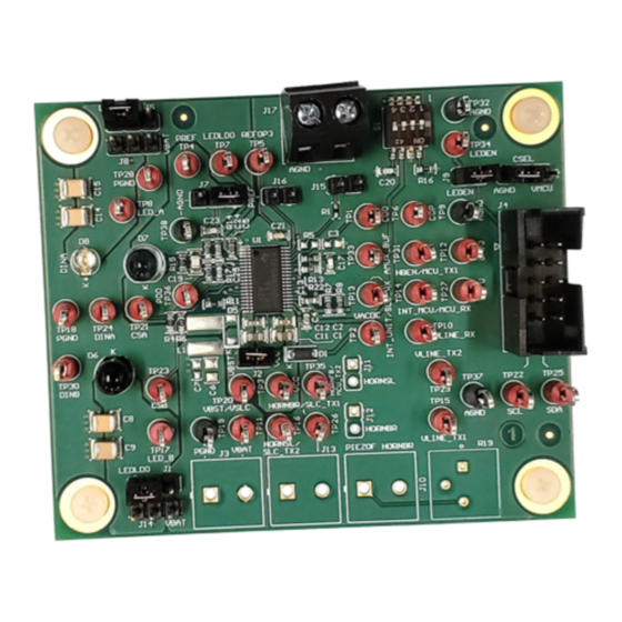
The TPS8804EVM is used to evaluate the TPS8804 smoke and CO detector analog front end (AFE) and
power management IC. The EVM allows for easy connection from the TPS8804 to a user-supplied
photoelectric chamber and carbon monoxide sensor. The TPS8804 GUI interfaces with the EVM to quickly
evaluate the photo amplifier, LED driver, and CO amplifier performance, and other blocks with the register
map. For a more thorough evaluation, an external microcontroller can be connected to the TPS8804EVM
to create a smoke detection system.
1.1
Applications
•
Smoke and CO detectors
1.2
Features
•
Dual LED drivers for blue and IR LEDs
•
Wide bandwidth, low offset photodiode amplifier
•
Ultra-low power CO transimpedance amplifier
•
LDOs for internal analog blocks and external microcontroller
•
Single buffered analog output AMUX for CO and photo signals
•
Serial interface for configuring amplifiers, drivers, regulators
•
SLC interface for power line communication
•
Under-voltage, over-temperature fault monitors
•
Wide input voltage range for flexible power supply configuration
1.3
Recommended Equipment
•
4.5-V to 15.5-V power supply capable of 100mA
•
USB2ANY™ interface adaptor
•
TPS880x GUI software
– Installation files are available in the TPS8804EVM product folder
•
Multimeter for measuring regulator voltages and CO amplifier output
•
Oscilloscope for measuring photodiode signal pulse shape
2
Setup
Specific connections on the TPS8804EVM board require configuration before starting the evaluation.
2.1
Sensor Connections
TI recommends connecting a photoelectric smoke chamber and CO sensor to the TPS8804EVM for the
evaluation. The TPS8804EVM has a built-in photodiode (D7), blue LED (D8), and IR LED (D6) for
functional testing. These components can be de-soldered in order to connect a photoelectric chamber
photodiode, IR LED, and/or blue LED its place. Ensure the photodiode wires are kept short to preserve
signal integrity.
SLVUBT6A – October 2019 – Revised May 2020
Submit Documentation Feedback
Copyright © 2019–2020, Texas Instruments Incorporated
SLVUBT6A – October 2019 – Revised May 2020
Using the TPS8804EVM
Using the TPS8804EVM
User's Guide
1
Advertisement

Related Manuals for Texas Instruments TPS8804EVM


Summary of Contents for Texas Instruments TPS8804EVM
- Page 1 Using the TPS8804EVM Introduction The TPS8804EVM is used to evaluate the TPS8804 smoke and CO detector analog front end (AFE) and power management IC. The EVM allows for easy connection from the TPS8804 to a user-supplied photoelectric chamber and carbon monoxide sensor. The TPS8804 GUI interfaces with the EVM to quickly evaluate the photo amplifier, LED driver, and CO amplifier performance, and other blocks with the register map.
- Page 2 0x3F. Connect J6 to the VMCU position to set the address to 0x2A. The GUI is compatible with both options and defaults to 0x2A. Using the TPS8804EVM SLVUBT6A – October 2019 – Revised May 2020 Submit Documentation Feedback Copyright © 2019–2020, Texas Instruments Incorporated...
-
Page 3: Power Connection
1.5 V • 1.8 V • 2.5 V • 3.3 V Table 1 for more information on the initial VMCU voltage. SLVUBT6A – October 2019 – Revised May 2020 Using the TPS8804EVM Submit Documentation Feedback Copyright © 2019–2020, Texas Instruments Incorporated... - Page 4 Figure 2). With the EVM powered, connect the USB2ANY adapter to the EVM using the USB2ANY adapter 10-pin ribbon cable. Click EXPLORE TPS8804EVM then QUICK START and select the device address corresponding to the J6 jumper (see Section 2.2). Send the test command to verify the EVM, USB2ANY adapter, and GUI software are all connected.
- Page 5 Click START EVALUATION and select the feature to evaluate. The Analog Front End section guides the CO AFE and photo AFE evaluation. Enter the register map to evaluate the other blocks in the TPS8804 device. SLVUBT6A – October 2019 – Revised May 2020 Using the TPS8804EVM Submit Documentation Feedback Copyright © 2019–2020, Texas Instruments Incorporated...
- Page 6 If a CO sensor is available, connect it to the J17 terminal block. Select the feedback resistance and reference voltage in the GUI software. The TPS8804EVM default configuration uses the internal resistors and references. To use an external feedback resistor, solder a resistor to R5. To use an external input resistor, replace the R1 0-Ω...
- Page 7 Analog Evaluation www.ti.com Figure 5. CO Amplifier Settings Figure 6. Clean Air CO Amplifier Output SLVUBT6A – October 2019 – Revised May 2020 Using the TPS8804EVM Submit Documentation Feedback Copyright © 2019–2020, Texas Instruments Incorporated...
- Page 8 CO sensor and amplifier. The AMUX pulse shape is different if the CO sensor is disconnected. Write COTEST_EN = 0, remove the J15 and J16 shunts, and connect the J7 shunt when finished. Using the TPS8804EVM SLVUBT6A – October 2019 – Revised May 2020 Submit Documentation Feedback Copyright © 2019–2020, Texas Instruments Incorporated...
- Page 9 Analog Evaluation www.ti.com Figure 8. COTEST_EN Register Bit SLVUBT6A – October 2019 – Revised May 2020 Using the TPS8804EVM Submit Documentation Feedback Copyright © 2019–2020, Texas Instruments Incorporated...
- Page 10 Analog Evaluation www.ti.com Figure 9. CO Connectivity Test without Sensor Using the TPS8804EVM SLVUBT6A – October 2019 – Revised May 2020 Submit Documentation Feedback Copyright © 2019–2020, Texas Instruments Incorporated...
- Page 11 20x, or 35x. The 470 kΩ resistor changes the PREF voltage to 70mV and prevents the gain stage output from dropping below 50mV in worst-case conditions. SLVUBT6A – October 2019 – Revised May 2020 Using the TPS8804EVM Submit Documentation Feedback Copyright © 2019–2020, Texas Instruments Incorporated...
- Page 12 J5, J8, and J14 jumpers to select which supply powers each LED. Enable the LEDLDO if it powers either LED. Using the TPS8804EVM SLVUBT6A – October 2019 – Revised May 2020 Submit Documentation Feedback Copyright © 2019–2020, Texas Instruments Incorporated...
- Page 13 Set the DAC voltage to fine tune the LED current. Set the temperature coefficient to the required setting. Click SETUP TEST after configuring the photo amplifier, LED power supply, and LED driver. SLVUBT6A – October 2019 – Revised May 2020 Using the TPS8804EVM Submit Documentation Feedback Copyright © 2019–2020, Texas Instruments Incorporated...
- Page 14 Probe LEDEN to measure the LED control signal. Probe CSA or CSB to measure the LED driver current. Probe PDO to measure the photo input stage amplifier. Probe AMUX_BUF to measure the photo gain stage amplifier. Using the TPS8804EVM SLVUBT6A – October 2019 – Revised May 2020 Submit Documentation Feedback Copyright © 2019–2020, Texas Instruments Incorporated...
- Page 15 Analog Evaluation www.ti.com Figure 14. EVM Photo Measurement Probe Configuration SLVUBT6A – October 2019 – Revised May 2020 Using the TPS8804EVM Submit Documentation Feedback Copyright © 2019–2020, Texas Instruments Incorporated...
- Page 16 Analog Evaluation www.ti.com Figure 15. LED A Signals Using the TPS8804EVM SLVUBT6A – October 2019 – Revised May 2020 Submit Documentation Feedback Copyright © 2019–2020, Texas Instruments Incorporated...
- Page 17 Analog Evaluation www.ti.com Figure 16. LED B Signals SLVUBT6A – October 2019 – Revised May 2020 Using the TPS8804EVM Submit Documentation Feedback Copyright © 2019–2020, Texas Instruments Incorporated...
-
Page 18: Register Map
Load and save register map configurations in the File menu. Click the question mark icon (?) to display more information about the selected register or bits. Using the TPS8804EVM SLVUBT6A – October 2019 – Revised May 2020 Submit Documentation Feedback Copyright © 2019–2020, Texas Instruments Incorporated... - Page 19 Analog Evaluation www.ti.com Figure 18. Register Map Search Function SLVUBT6A – October 2019 – Revised May 2020 Using the TPS8804EVM Submit Documentation Feedback Copyright © 2019–2020, Texas Instruments Incorporated...
-
Page 20: Board Layout
Board Layout www.ti.com Board Layout Figure 19. TPS8804EVM Top Layer PCB Layout Using the TPS8804EVM SLVUBT6A – October 2019 – Revised May 2020 Submit Documentation Feedback Copyright © 2019–2020, Texas Instruments Incorporated... - Page 21 Board Layout www.ti.com Figure 20. TPS8804EVM Ground Layer PCB Layout SLVUBT6A – October 2019 – Revised May 2020 Using the TPS8804EVM Submit Documentation Feedback Copyright © 2019–2020, Texas Instruments Incorporated...
- Page 22 Board Layout www.ti.com Figure 21. TPS8804EVM Power Layer PCB Layout Using the TPS8804EVM SLVUBT6A – October 2019 – Revised May 2020 Submit Documentation Feedback Copyright © 2019–2020, Texas Instruments Incorporated...
- Page 23 Board Layout www.ti.com Figure 22. TPS8804EVM Bottom Layer PCB Layout SLVUBT6A – October 2019 – Revised May 2020 Using the TPS8804EVM Submit Documentation Feedback Copyright © 2019–2020, Texas Instruments Incorporated...
-
Page 24: Schematic And Bill Of Materials
Capacitor, ceramic, 47 µF, 16 V, ±20%, X6S, 1210 1210 E15L 100 pF Capacitor, ceramic, 100 pF, 16 V, ±10%, X7R, 0402 0402 0402YC101KAT2A Using the TPS8804EVM SLVUBT6A – October 2019 – Revised May 2020 Submit Documentation Feedback Copyright © 2019–2020, Texas Instruments Incorporated... - Page 25 Resistor, 10 M, 5%, 0.1 W, AEC-Q200 Grade 0, 0603 0603 SW, SMT Half 218-4LPST Pitch 4SPST, Switch, Slide, SPST 4 poles, SMT 5.8×2.7×6.25 SLVUBT6A – October 2019 – Revised May 2020 Using the TPS8804EVM Submit Documentation Feedback Copyright © 2019–2020, Texas Instruments Incorporated...
- Page 26 TP9, TP18, 5011 Black TP19, TP28, Test Point, Multipurpose, Black, TH Multipurpose TP32, TP37, Testpoint TP38 TPS8804DCP, DCP0038A (HTSSOP-38) DCP0038A TPS8804DCP Using the TPS8804EVM SLVUBT6A – October 2019 – Revised May 2020 Submit Documentation Feedback Copyright © 2019–2020, Texas Instruments Incorporated...
-
Page 27: Revision History
................... • Changed R13 value to 10.0 kΩ in Table 2 ....................• Deleted R15, C19, TP5, TP6 in Table 2 SLVUBT6A – October 2019 – Revised May 2020 Revision History Submit Documentation Feedback Copyright © 2019–2020, Texas Instruments Incorporated... - Page 28 TI products. TI’s provision of these resources does not expand or otherwise alter TI’s applicable warranties or warranty disclaimers for TI products. Mailing Address: Texas Instruments, Post Office Box 655303, Dallas, Texas 75265 Copyright © 2020, Texas Instruments Incorporated...
Need help?
Do you have a question about the TPS8804EVM and is the answer not in the manual?
Questions and answers