Advertisement
LC4H-SV
48
1.890
48
1.890
R4 / T4 systems (4-digit display)
R6 / T6 systems (6-digit display)
Pin type
Screw terminal type
PRODUCT TYPES
Digit
Count speed
Output
Relay
4
Transistor
30 Hz (cps)
5 kHz (kcps)
switchable
Relay
6
Transistor
* A rubber gasket (ATC18002) and a mounting frame (AT8-DA4) are included.
82
new:
DIN 48 SIZE
LCD ELECTRONIC COUNTER
Scale factor, power supply
NEW FEATURES:
1. Scale Factor:
A scale factor can be entered into LC4H-SV
series. After that one count shows the real
unit/value of the machine/application.
2. 12 V DC Power Supply:
The 100 – 240 V AC types are equipped
64.5
2.539
mm
inch
FEATURES
1. Bright and Easy-to-Read Display
A brand new bright 2-color backlight LCD
display. The easy-to-read screen in any
location makes checking and setting pro-
cedures a cinch.
2. Simple Operation
Seesaw buttons make operating the unit
even easier than before.
3. Conforms to IP66's Weather
Resistant Standards
The water-proof panel keeps out water
and dirt for reliable operation even in
poor environments.
Operation voltage
Power down
insurane
100-240 V AC
with 12V DC power supply
12-24 V DC / 24 V AC
100-240 V AC
with 12V DC power supply
12-24 V DC / 24 V AC
Additional function
Scale Factor
Scale Factor
Scale Factor / Voltage Signal Input
Scale Factor / Voltage Signal Input
Scale Factor
Scale Factor
Scale Factor / Voltage Signal Input
Scale Factor / Voltage Signal Input
Scale Factor
Scale Factor
Scale Factor / Voltage Signal Input
Available
Scale Factor / Voltage Signal Input
Scale Factor
Scale Factor
Scale Factor / Voltage Signal Input
Scale Factor / Voltage Signal Input
Scale Factor
Scale Factor
Scale Factor / Voltage Signal Input
Scale Factor / Voltage Signal Input
Scale Factor
Scale Factor
Scale Factor / Voltage Signal Input
Scale Factor / Voltage Signal Input
02/2003
LC4H-S
with a 12 V DC power supply 100 mA.
It is possible to connect photo-sensors,
proximity switches or encoders without addi-
tional devices.
3. Voltage Signal Input:
PNP input types are available.
4. Screw terminal and Pin Type are
Both Standard Options
The two terminal types are standard
options to support either front panel
installation or embedded installation.
5. 4-digit or 6-digit display
Two sizes of displays are offered for you
to choose the one that suits your needs.
6. Conforms With EMC and Low
Voltage Directives
Conforms with EMC directives
(EN50081-2/EN50082-2) and low-volt-
age directives (VDE0435/Part 2021) for
CE certification vital for use in Europe.
Terminal
11 Pin
LC4H-PS-R4-AC240V
Screw
LC4H-PS-R4-AC240VS
11 Pin
LC4H-PSV-R4-AC240V
Screw
LC4H-PSV-R4-AC240VS
11 Pin
LC4H-S-R4-24V
Screw
LC4H-S-R4-24VS
11 Pin
LC4H-SV-R4-24V
Screw
LC4H-SV-R4-24VS
11 Pin
LC4H-S-T4-24V
Screw
LC4H-S-T4-24VS
11 Pin
LC4H-SV-T4-24V
Screw
LC4H-SV-T4-24VS
11 Pin
LC4H-PS-R6-AC240V
Screw
LC4H-PS-R6-AC240VS
11 Pin
LC4H-PSV-R6-AC240V
Screw
LC4H-PSV-R6-AC240VS
11 Pin
LC4H-S-R6-24V
Screw
LC4H-S-R6-24VS
11 Pin
LC4H-SV-R6-24V
Screw
LC4H-SV-R6-24VS
11 Pin
LC4H-S-T6-24V
Screw
LC4H-S-T6-24VS
11 Pin
LC4H-SV-T6-24V
Screw
LC4H-SV-T6-24VS
P/N
Advertisement
Table of Contents

Related Manuals for Panasonic LC4H-S Series


Summary of Contents for Panasonic LC4H-S Series
- Page 1 LC4H-SV new: DIN 48 SIZE LC4H-S LCD ELECTRONIC COUNTER Scale factor, power supply NEW FEATURES: 1. Scale Factor: with a 12 V DC power supply 100 mA. A scale factor can be entered into LC4H-SV It is possible to connect photo-sensors, series.
-
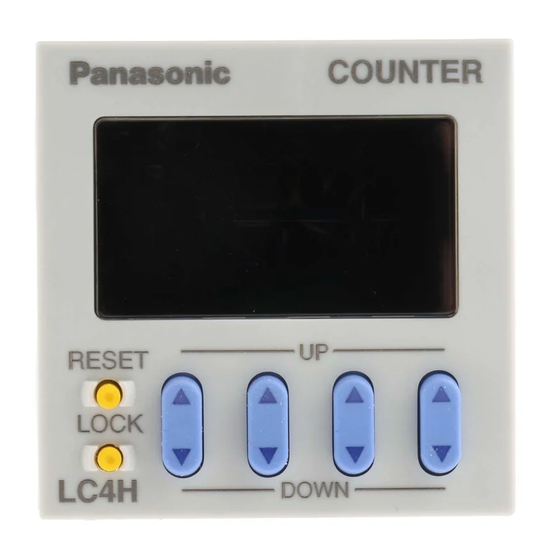
Page 2: Part Names
LC4H-S Part names • 4-digit display type DIP switches COUNTER LC4H Counter display Controlled output indicator Set value display O P . Reset indicator R S T L O C K Lock indicator RESET Up keys Reset switch SET/ LOCK Down keys Set/lock switch DOWN... - Page 3 LC4H-S Dimensions (units: mm inch) Pin type Screw-down terminal type 70.1 14.5 2.760 .571 .217 .217 64.5 55.6 (1.890 2.539 2.189 C O U N T E R L C 4 H ((44.5) ((1.752) ((44.5) ((1.752) (1.890 RESET SET/LOCK DOWN .295 81.9* 2.874*...
- Page 4 LC4H-S Setting the operation mode and counter Setting procedure 1) Setting the operation mode (input mode and output mode) Set the input and output modes with the DIP switches on the side of the counter. DIP switches Table 1: Setting the output mode DIP switch DIP switch No.
-
Page 5: Changing The Set Value
LC4H-S E The decimal point is set using the [UP] and [DOWN] keys to specify the 2nd, 3rd, and 4th digits (this applies only to 4-digit models).(The 1st digit is set using the [UP] key or [DOWN] key in settings where there is no decimal point (this applies only to 4-digit models).) Example) 6-digit type Example shows 2nd digit displayed using [UP] key... -
Page 6: Operation Mode
LC4H-S Operation mode 1. Input mode For the input mode, you can choose one of the following five modes • Addition • Subtraction DOWN • Directive • Independent • Phase PHASE Input mode Operation *Minimum input signal width 30 Hz: 16.7 ms; 5 kHz: 0.1 ms IN1 or IN2 works as an input block •... - Page 7 LC4H-S 2. Output mode For the output mode, you can choose one of the following seven modes • Maintain output/hold count HOLD-A • Maintain output/over count I HOLD-B • Maintain output/over count II HOLD-C • One shot/over count SHOT-A • One shot/recount I SHOT-B •...
-
Page 8: Input Connections
LC4H-S Input connections • Signal input type •) Open collector •) For voltage output (Photoelectric sensor, (PC, sensor etc.) proximity sensor, etc.) 12 V DC 12 V DC Output Output – – 11-pin type 11-pin type Screw-down Screw-down terminal type terminal type Lock Input... - Page 9 LC4H series CAUTIONS FOR USE PRECAUTIONS DURING USAGE 1. Terminal wiring age of less than 2 V when the transistor ( Fig. B ) 1) When wiring the terminals, refer to the Input contact is on. point or transistor terminal layout and wiring diagrams and * The short-circuit impedance should be be sure to perform the wiring properly Input...
- Page 10 device, use a single-phase or double- 4. Output mode setting phase insulated power transformer. The The output mode can be set with the second-phase side must not be ground- switches on the side of the counter. Leakage current Make the DIP switch settings before Operation power supply 4) Since the power supply circuitry does installing the counter on the panel.
- Page 11 6. Self-diagnosis function If a malfunction occurs, one of the following displays will appear. Display Contents Output condition Restoration procedure Preset values after restoration Minimum value went below –999 Enter reset or RESET or –99999. See note 1. key. No change No change Restart unit (correct DIP Incorrect DIP switch setting.
Need help?
Do you have a question about the LC4H-S Series and is the answer not in the manual?
Questions and answers