Vega VEGACAL 67 Operating Instructions Manual
Foundation fieldbus
Hide thumbs
Also See for VEGACAL 67:
- Operating instructions manual (60 pages) ,
- Operating instructions manual (36 pages)
Table of Contents
Advertisement
Quick Links
Advertisement
Table of Contents

Related Manuals for Vega VEGACAL 67


Summary of Contents for Vega VEGACAL 67
- Page 1 Operating Instructions VEGACAL 67 Foundation Fieldbus...
-
Page 2: Table Of Contents
Setup procedure ..... . . Menu schematic ..... . . VEGACAL 67 - Foundation Fieldbus... - Page 3 10.3 Dimensions ......10.4 Industrial property rights....VEGACAL 67 - Foundation Fieldbus...
-
Page 4: About This Document
This symbol indicates special instructions for Ex applications. List The dot set in front indicates a list with no implied sequence. à Action This arrow indicates a single action. Sequence Numbers set in front indicate successive steps in a procedure. VEGACAL 67 - Foundation Fieldbus... -
Page 5: For Your Safety
2.4 General safety instructions The VEGACAL 67 is a high-tech instrument requiring the strict observance of standard regulations and guidelines. The user must take note of the safety instructions in this operating instructions manual, the country-specific installation standards... -
Page 6: Manufacturer Declaration
2.7 Manufacturer declaration In conformity with DIN EN 60079-14/2004, para. 5.2.3, point c1, the capacitive probe VEGACAL 67 is suitable for use in zone 2. The operator must use the instrument correctly and follow the specifications of the following documents:... -
Page 7: Environmental Instructions
The environment man- agement system is certified acc. to DIN EN ISO 14001. Please help us fulfil this obligation by observing the environ- mental instructions in this manual: Chapter "Storage and transport" Chapter "Disposal" VEGACAL 67 - Foundation Fieldbus... -
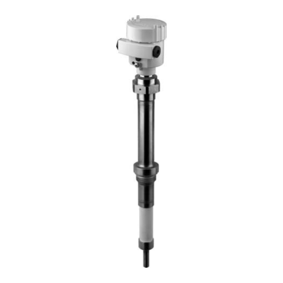
Page 8: Product Description
VEGACAL 67 level sensor documentation - this operating instructions manual - Ex-specific safety instructions (with Ex versions), if necessary further certificates. VEGACAL 67 consists of the following components: Components Process fitting with probe Housing with electronics Housing cover, optionally available with indicating and... -
Page 9: Principle Of Operation
Housing with electronics Process fitting Ceramic insulator 3.2 Principle of operation VEGACAL 67 is a level sensor with partly insulated electrode Area of application for continuous level measurement under high process tem- peratures. The electronics functions acc. to the admittance principle (phase-selective admittance processing). - Page 10 Product description Probes such as VEGACAL 67 are used in solids applications. The range of the process temperature is -50 … 300°C (-58 … 572°F). With remote housing -50 … 400°C (-58 … 752°F). The probe, the measured product and the vessel wall form an Physical principle electrical capacitor.
-
Page 11: Adjustment
A CD with the appropriate files and certificates can be ordered via e-mail under info@de.vega.com or by phone from one of the VEGA agencies under the order number "DRIVER.S". The optional heating requires an own supply voltage. Details are specified in the supplementary instructions manual... -
Page 12: Mounting
Use the recommended cables (see chapter "Connecting to Moisture power supply") and tighten the cable gland. You can give your VEGACAL 67 additional protection against moisture penetration by leading the connection cable down- ward in front of the cable entry. Rain and condensation water can thus drain off. -
Page 13: Mounting Information
Use a concentric tube in non-conductive products or linearize the meas. signal. 4.2 Mounting information If VEGACAL 67 is mounted in the filling stream, unwanted Inflowing material switching signals may be generated. Mount VEGACAL 67 at a location in the vessel where no disturbing influence from e.g. - Page 14 Make sure that the max. permissible tensile load of the Tensile load suspension cable is not exceeded. The danger of this happening exists particularly with very heavy solids and large meas. lengths. The max. permissible load is stated under "Technical data" in the "Supplement". VEGACAL 67 - Foundation Fieldbus...
-
Page 15: Connecting To Power Supply
If overvoltages are expected, overvoltage arresters should be installed acc. to Foundation Fieldbus specification. VEGACAL 67 requires a power supply of 9 … 32 V DC. Power Select power supply and the digital bus signal are carried on the same two-wire connection cable. -
Page 16: Connection Steps
Fig. 5: Connection steps 6 and 7 8 Press the opening lever of the terminals downward, you will hear the terminal spring closing 9 Check the hold of the wires in the terminals by lightly pulling on them VEGACAL 67 - Foundation Fieldbus... -
Page 17: Wiring Plans, Single Chamber Housing
5.3 Wiring plans, single chamber housing Housing overview Fig. 6: Material versions, single chamber housing Plastic Aluminium Stainless steel Filter element for pressure compensation or blind stopper with version IP 66/ IP 68, 1 bar VEGACAL 67 - Foundation Fieldbus... - Page 18 Ground terminal for connection of the cable screen Spring-loaded terminals for Foundation Fieldbus connection Simulation switch ("on" = mode for simulation release) Wiring plan Display I 2 C Fig. 8: Wiring plan, single chamber housing Power supply/Signal output VEGACAL 67 - Foundation Fieldbus...
-
Page 19: Wiring Plans, Double Chamber Housing
Fig. 10: Electronics compartment, double chamber housing Simulation switch ("on" = mode for simulation release) Connection for VEGACONNECT (I²C interface) Internal connection cable to the connection compartment Version IP 66/IP 68, 1 bar not with four-wire instruments. VEGACAL 67 - Foundation Fieldbus... - Page 20 Fig. 11: Connection compartment, double chamber housing Plug connector for VEGACONNECT (I²C interface) Ground terminal for connection of the cable screen Spring-loaded terminals for power supply Wiring plan I 2 C Fig. 12: Wiring plan, double chamber housing Power supply/Signal output VEGACAL 67 - Foundation Fieldbus...
-
Page 21: Wiring Plans, Version Ip 66/Ip 68 (1 Bar)
Connecting to power supply 5.5 Wiring plans, version IP 66/IP 68 (1 bar) Wire assignment, connection cable Fig. 13: Wire assignment, connection cable br (+) and bl (-) for power supply or to the processing system Screen VEGACAL 67 - Foundation Fieldbus... -
Page 22: Setup With The Indicating And Adjustment Module Plicscom
4 Screw housing cover with inspection window tightly back Removal is carried out in reverse order. PLICSCOM is powered by the sensor, an additional con- nection is not necessary. VEGACAL 67 - Foundation Fieldbus... - Page 23 Setup with the indicating and adjustment module PLICSCOM Fig. 14: Installation of PLICSCOM Note: If you intend to retrofit VEGACAL 67 with a PLICSCOM for continuous measured value indication, a higher cover with an inspection glass is required. VEGACAL 67 - Foundation Fieldbus...
-
Page 24: Adjustment System
The functions of the individual keys are shown in the above illustration. Approx. 10 minutes after the last pressing of a key, an automatic reset to measured value indication is triggered. Any values not confirmed with [OK] will not be saved. VEGACAL 67 - Foundation Fieldbus... -
Page 25: Setup Procedure
Setup with the indicating and adjustment module PLICSCOM 6.4 Setup procedure After VEGACAL 67 is connected to voltage supply or after Switch-on phase voltage recurrence, the instrument carries out a self-test for approx. 30 seconds. The following steps are carried out: Internal check of the electronics Indication of the instrument type, the firmware version as... - Page 26 [OK]. Now the menu item "Min. adjustment" is displayed. Min. adjustment 0.00 % 0.0 pF 54.5 pF 3 Prepare the adjustment value for editing with [OK]. Move to the selection window with [OK]. VEGACAL 67 - Foundation Fieldbus...
- Page 27 [OK]. The cursor jumps to the capacitance value. 3 Enter the current capacitance value in pF (displayed below) for the full vessel corresponding to the percentage value. 4 Save the settings with [OK]. VEGACAL 67 - Foundation Fieldbus...
- Page 28 Sensor-TAG Sensor With this menu item, the Basic adjustment is finished and you can now jump to the main menu with the [ESC] key. VEGACAL 67 - Foundation Fieldbus...
- Page 29 0 pF Integration time ti Linearization linear Sensor-TAG Sensor Display AI-Out 1 Special parameters All special parameters are reset to delivery status. Peak values The min. and max. values are reset to the current value. VEGACAL 67 - Foundation Fieldbus...
-
Page 30: Menu Schematic
Basic adjustment ▶ Display Diagnostics Service Info Displayed value Al-Out Diagnostics Basic adjustment Display ▶ Diagnostics Service Info Peak values Sensor status Trend recording Capacitance-min.: 65.7 pF Presentation of the out- Capacitance-max.: 782.4 pF put trend VEGACAL 67 - Foundation Fieldbus... - Page 31 Date of last change using PC < max. 32 characters > VEGACAL 6x 04. February 2005 Sensor-TAG (PD_TAG) Serial number Software version 04. March 2005 < max. 32 characters > 12345678 4.10/00 Sensor characteristics Display now? VEGACAL 67 - Foundation Fieldbus...
-
Page 32: Setup With Pactware™ And Other Adjustment Programs
A detailed description is available in the online help of PACTware™ and the VEGA-DTMs. Note: Keep in mind that for setup of VEGACAL 67, DTM-Collection 04/2005 or a newer version must be used. VEGACAL 67 - Foundation Fieldbus... -
Page 33: Parameter Adjustment With Ams
All currently available VEGA-DTMs are provided in the DTM Collection on CD and can be obtained from the responsible VEGA agency for a token fee. This CD includes also the up-to- date PACTware™ version. The basic version of this DTM Collection incl. -
Page 34: Maintenance And Fault Rectification
Maintenance and fault rectification 8 Maintenance and fault rectification 8.1 Maintenance When used as directed in normal operation, VEGACAL 67 is completely maintenance-free. 8.2 Fault rectification VEGACAL 67 offers maximum reliability. Nevertheless faults Causes of malfunction can occur during operation. These may be caused by the following, e.g.:... - Page 35 Fig. 17: Check the resistance in the probe Screen Probe Ground potential à There should be no contact between any of the connections (high resistance) à However, if there is somehow contact, exchange instrument or return it for repair VEGACAL 67 - Foundation Fieldbus...
-
Page 36: Exchange Of The Electronics Module
Ex approval may be used. If there is no electronics module available on site, one can be ordered from the VEGA agency serving you. The order data of the sensor must be loaded into the new Sensor serial number electronics module. -
Page 37: Shorten The Probe
If it is necessary to repair, please proceed as follows: You can download a return form (23 KB) in the Internet from our home page www.vega.com under: "Downloads - Forms and Certificates - Repair form". By doing this you help us carry out the repair quickly and without having to call back for needed information. -
Page 38: Dismounting
Correct disposal avoids negative effects to persons and environment and ensures recycling of useful raw materials. Materials: see "Technical data" If you cannot dispose of the instrument properly, please contact us about disposal methods or return. VEGACAL 67 - Foundation Fieldbus... -
Page 39: Supplement
Max. tensile load (cable) - Ceramic partly insulated ø 8 mm 10 KN (2248 lbs) (ø 0.32 in) Max. torque (process fitting thread) 80 Nm (58 lbf ft) Cable connected electrically conductive with the gravity weight. VEGACAL 67 - Foundation Fieldbus... - Page 40 - >120 pF 1 % of the current measured value Linearity error <0.25 % of the complete measuring range Characteristic curve deviation and measurement characteristics Temperature drift 0.06 %/10 K relating to the max. measuring range VEGACAL 67 - Foundation Fieldbus...
- Page 41 - with remote housing -50 … +400°C (-58 … +752°F) -50° 0° 100° 200° 300° 400° °C Fig. 18: Product temperature - Process pressure Product temperature Process pressure Temperature range with remote housing Dielectric figure >1.5 VEGACAL 67 - Foundation Fieldbus...
- Page 42 M20x1.5; plug M12x1 for VEGADIS 61 (option) 1x closing cap ½ NPT, 1x blind stopper ½ NPT, plug M12x1 for VEGADIS 61 (optional) Depending on the version M12x1, acc. to DIN 43650, Harting, Amphenol- Tuchel, 7/8" FF VEGACAL 67 - Foundation Fieldbus...
- Page 43 Supply voltage - non-Ex instrument 9 … 32 V DC - EEx ia instrument 9 … 24 V DC Power supply by/max. number of sensors - H1 power supply max. 32 (max. 10 with Ex) VEGACAL 67 - Foundation Fieldbus...
- Page 44 - Alu and stainless steel standard IP 66/IP 68 (0.2 bar) - Alu and stainless housing, optionally IP 66/IP 68 (1 bar) available Overvoltage category Protection class Requirement to maintain the protection is the suitable cable. VEGACAL 67 - Foundation Fieldbus...
-
Page 45: Foundation Fieldbus
Channel = 1: Primary Value AI 2 Channel = 2: Secondary Value 1 Channel = 3: Secondary Value 2 Fig. 19: VEGACAL 67 measured value processing Diagram, adjustment The following illustration shows the function of the adjustment: VEGACAL 67 - Foundation Fieldbus... - Page 46 Highest Point cal_level_lo [%] Calibration Lowest Point Fig. 20: Adjustment VEGACAL 67 Parameter list The following list contains the most important parameters and their meaning: primary_value - This is the process value after adjustment and Linearization with the status of the...
- Page 47 - Min./Max. adjustment: this is the value of level at "Calibration Highest Point". The unit is defined in "level_unit". When writing "cal_level_hi" and "cal_type" = 1, the "Calibration Highest Point" is automatically set to "sensor_value". VEGACAL 67 - Foundation Fieldbus...
- Page 48 VEGACAL 67 - Foundation Fieldbus...
-
Page 49: Dimensions
M20x1,5 M20x1,5 M20x1,5/ ½ NPT Fig. 22: Housing versions in protection IP 66/IP 68, 1 bar (with integrated PLICSCOM the housing is 9 mm/0.35 in higher) Stainless steel housing Aluminium double chamber housing Aluminium housing VEGACAL 67 - Foundation Fieldbus... - Page 50 NPT1 ½ ø 8mm ") ø 40mm ø 15mm ") ") Fig. 23: VEGACAL 67 - Threaded version G1½ A and 1½ NPT = Sensor length, see "Technical data" L1 Supporting tube length, see "Technical data" VEGACAL 67 - Foundation Fieldbus...
-
Page 51: Industrial Property Rights
Les lignes de produits VEGA sont globalement protégées par des droits de propriété intellectuelle. Pour plus d'informations, on pourra se référer au site http://www.vega.com. VEGA lineas de productos están protegidas por los derechos en el campo de la propiedad industrial. Para mayor información revise la pagina web http://www.vega.com. - Page 52 All statements concerning scope of delivery, application, practical use and operating conditions of the sensors and processing systems correspond to the information avail- able at the time of printing. © VEGA Grieshaber KG, Schiltach/Germany 2006 Technical data subject to alterations 31760-EN-060306...
Need help?
Do you have a question about the VEGACAL 67 and is the answer not in the manual?
Questions and answers