Vega VEGACAL 65 Operating Instructions Manual
Capacitive cable electrode for continuous level measurement
Hide thumbs
Also See for VEGACAL 65:
- Operating instructions manual (64 pages) ,
- Safety manual (16 pages) ,
- Operating instructions manual (40 pages)

Related Manuals for Vega VEGACAL 65


Summary of Contents for Vega VEGACAL 65
- Page 1 Operating Instructions Capacitive cable electrode for continuous level measurement VEGACAL 65 Two-wire 4 … 20 mA/HART Document ID: 30033...
-
Page 2: Table Of Contents
Parameter adjustment with PACTware ................39 Parameter adjustment with AMS™ and PDM ..............40 Saving the parameterisation data ................... 41 Set up with smartphone/tablet/PC/notebook via Bluetooth ..........42 Preparations ........................42 Connecting ........................43 VEGACAL 65 • Two-wire 4 … 20 mA/HART... - Page 3 10.1 Dismounting steps......................50 10.2 Disposal ......................... 50 11 Supplement ..........................51 11.1 Technical data ........................ 51 11.2 Dimensions ........................57 11.3 Industrial property rights ....................62 11.4 Trademark ........................62 Editing status: 2020-09-24 VEGACAL 65 • Two-wire 4 … 20 mA/HART...
-
Page 4: About This Document
Symbols used Document ID This symbol on the front page of this instruction refers to the Docu- ment ID. By entering the Document ID on www.vega.com you will reach the document download. Information, note, tip: This symbol indicates helpful additional infor- mation and tips for successful work. -
Page 5: For Your Safety
During work on and with the device, the required personal protective equipment must always be worn. Appropriate use VEGACAL 65 is a sensor for continuous level measurement. You can find detailed information about the area of application in chapter " Product description". Operational reliability is ensured only if the instrument is properly used according to the specifications in the operating instructions manual as well as possible supplementary instructions. -
Page 6: Namur Recommendations
That is why we have introduced an environment management system with the goal of continuously improving company environmental pro- tection. The environment management system is certified according to DIN EN ISO 14001. Please help us fulfil this obligation by observing the environmental instructions in this manual: • Chapter " Packaging, transport and storage" • Chapter " Disposal" VEGACAL 65 • Two-wire 4 … 20 mA/HART... -
Page 7: Product Description
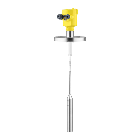
This operating instructions manual applies to the following instrument instructions versions: • Hardware from 1.0.0 • Software from 1.3.0 • Only for instrument versions without SIL qualification Constituent parts The VEGACAL 65 consists of the components: • Process fitting with probe • Housing with electronics • Housing lid VEGACAL 65 • Two-wire 4 … 20 mA/HART... - Page 8 3 Product description Fig. 1: VEGACAL 65, cable version with plastic housing Housing lid Housing with electronics 3 Process fitting Type label The type label contains the most important data for identification and use of the instrument: VEGACAL 65 • Two-wire 4 … 20 mA/HART...
- Page 9 Alternatively, you can access the data via your smartphone: • Download the VEGA Tools app from the " Apple App Store" or the " Google Play Store" • Scan the DataMatrix code on the type label of the instrument or •...
-
Page 10: Principle Of Operation
Principle of operation Application area VEGACAL 65 is a level sensor for use in all areas of industry. The partly insulated probe is ideal for measurement of bulk solids and can be also used in non-conductive liquids such as for example oil. -
Page 11: Packaging, Transport And Storage
3 Product description • With the display and adjustment module • with the suitable VEGA DTM in conjunction with an adjustment software according to the FDT/DTM standard, e.g. PACTware and • With manufacturer-specific adjustment programs AMS™ or PDM • With a HART handheld Packaging, transport and storage Packaging Your instrument was protected by packaging during transport. - Page 12 3 Product description The interface adapter VEGACONNECT enables the connection of VEGACONNECT communication-capable instruments to the USB interface of a PC. VEGADIS 81 The VEGADIS 81 is an external display and adjustment unit for VEGA plics sensors. ® VEGADIS 82 VEGADIS 82 is suitable for measured value indication and adjustment of sensors with HART protocol.
-
Page 13: Mounting
Applying tightening forces on the housing can damage its internal parts. Use the hexagon for screwing in. Protection against mois- Use the recommended cables (see chapter " Connecting to power ture supply") and tighten the cable gland. VEGACAL 65 • Two-wire 4 … 20 mA/HART... - Page 14 This applies particularly to applications in non-conductive products. In cylindrical tanks, spherical tanks or other asymmetrical tank forms, nonlinear level values are generated due to the varying distance to the vessel wall. VEGACAL 65 • Two-wire 4 … 20 mA/HART...
-
Page 15: Mounting Instructions
In the gravity weight there is a thread (M12), e.g. for a ring bolt (article no. 2.27424). The thread is already insulated in the gravity weight with an adapter. Make sure that the probe cable is not completely taut. Avoid tensile loads on the cable. VEGACAL 65 • Two-wire 4 … 20 mA/HART... - Page 16 For this reason, mount the instrument at a position in the vessel where no disturbances, e.g. from filling openings, agitators, etc., can occur. This applies particularly to instrument versions with a longer probe. Fig. 7: Inflowing medium VEGACAL 65 • Two-wire 4 … 20 mA/HART...
-
Page 17: Connecting To Power Supply
In the case of instrument housings with self-sealing NPT threads, it is not possible to have the cable entries screwed in at the factory. The free openings for the cable glands are therefore covered with red dust protection caps as transport protection. VEGACAL 65 • Two-wire 4 … 20 mA/HART... -
Page 18: Connection Procedure
5. Insert the cable into the sensor through the cable entry 6. Lift the opening levers of the terminals with a screwdriver (see following illustration) 7. Insert the wire ends into the open terminals according to the wir- ing plan VEGACAL 65 • Two-wire 4 … 20 mA/HART... -
Page 19: Wiring Plan, Single Chamber Housing
Fig. 9: Material versions, single chamber housing Plastic Aluminium Stainless steel (precision casting) Stainless steel (electro-polished) Filter element for air pressure compensation of all material versions. Blind plug with version IP66/IP68, 1 bar for Aluminium and stainless steel VEGACAL 65 • Two-wire 4 … 20 mA/HART... -
Page 20: Wiring Plan, Double Chamber Housing
I 2 C Fig. 11: Wiring plan - single chamber housing Voltage supply, signal output Wiring plan, double chamber housing The following illustrations apply to the non-Ex as well as to the Ex-ia version. VEGACAL 65 • Two-wire 4 … 20 mA/HART... - Page 21 Connection compartment I 2 C Fig. 14: Connection compartment - double chamber housing Spring-loaded terminals for voltage supply Plug connector for service (I²C interface) Ground terminal for connection of the cable screening VEGACAL 65 • Two-wire 4 … 20 mA/HART...
-
Page 22: Wiring Plan, Ex-D Double Chamber Housing
I 2 C 5 6 7 8 Fig. 17: Electronics compartment - double chamber housing Plug connector for VEGACONNECT (I²C interface) Internal connection cable to the connection compartment Terminals for VEGADIS 81 VEGACAL 65 • Two-wire 4 … 20 mA/HART... -
Page 23: Wiring Plan - Version Ip66/Ip68, 1 Bar
Wiring plan - version IP66/IP68, 1 bar Wire assignment, con- nection cable Fig. 20: Wire assignment, connection cable Brown (+) and blue (-) to power supply or to the processing system Shielding VEGACAL 65 • Two-wire 4 … 20 mA/HART... -
Page 24: Set Up With The Display And Adjustment Module Plicscom
Disassembly is carried out in reverse order. The display and adjustment module is powered by the sensor, an ad- ditional connection is not necessary. Fig. 21: Insert display and adjustment module in the single chamber housing VEGACAL 65 • Two-wire 4 … 20 mA/HART... -
Page 25: Adjustment System
1 s, the value or position changes continuously. When the [OK] and [ESC] keys are pressed simultaneously for more than 5 s, the display returns to the main menu. The menu language is then switched over to " English". VEGACAL 65 • Two-wire 4 … 20 mA/HART... -
Page 26: Setup Steps
The actual level can then be calculated on the basis of these settings. VEGACAL 65 must be installed. A change of level is necessary for this adjustment. In the main menu item " Basic adjustment", the individual submenu items should be selected one after the other and provided with the correct parameter values. - Page 27 5. Enter the current capacitance value in pF (displayed below) for the empty vessel corresponding to the percentage value. 6. Save the settings with [OK] and move to "Max. adjustment" with [->]. VEGACAL 65 • Two-wire 4 … 20 mA/HART...
- Page 28 If the volume should not be displayed in percent but e.g. in l or kg, a scaling can be also set in the menu item " Display". VEGACAL 65 • Two-wire 4 … 20 mA/HART...
- Page 29 Enter the requested parameters via the appropriate keys, save your settings and jump to the next menu item with the [->] key. Caution: Note the following if the VEGACAL 65 with corresponding approval is used as part of an overfill protection system according to WHG (Water Resources Act): If a linearisation curve is selected, the measuring signal is no longer necessarily linear to the filling height. This must be considered by the...
- Page 30 E013". The failure is also displayed in clear text, for example " No measured value available". Information: The fault message as well as the clear text indication are also carried out in the measured value display. VEGACAL 65 • Two-wire 4 … 20 mA/HART...
- Page 31 Min. current 3.8 mA Value of the current output in case of failure, e.g. if no valid measured value is delivered. This value is not underrun during operation. This value is not exceeded during operation. VEGACAL 65 • Two-wire 4 … 20 mA/HART...
- Page 32 Min. adjustment 0 pF Damping ti Linearisation Linear Sensor-TAG Sensor Display Current output - characteristics 4 … 20 mA Current output - max. current 20.5 mA Current output - min. current 3.8 mA VEGACAL 65 • Two-wire 4 … 20 mA/HART...
- Page 33 • Write parameter adjustment data from the display and adjustment module into the sensor The 4 … 20 mA signal of the sensor is switched off. The sensor uses a constant current of 4 mA. The measuring signal is transmitted exclusively as a digital HART signal. VEGACAL 65 • Two-wire 4 … 20 mA/HART...
- Page 34 • Instrument type • Serial number: 8-digit number, e.g. 12345678 Instrument type Serial number • Date of manufacture: Date of the factory calibration • Software version: Edition of the sensor software VEGACAL 65 • Two-wire 4 … 20 mA/HART...
-
Page 35: Menu Schematic
Menu schematic Basic adjustment ▶ Basic adjustment Display Diagnostics Service Info Min. adjustment Max. adjustment Damping Linearisation curve 0.00 % 100.00 % Linear 0.0 pF 1000.0 pF 82.5 pF 327.4 pF Sensor-TAG Sensor VEGACAL 65 • Two-wire 4 … 20 mA/HART... - Page 36 ► Characteristic: 4-20 mA ► ► Start simulation? Select reset? Deutsch Fail.mode: < 3.6 mA ► min. current: 4 mA HART mode Copy sensor data Standard Address 0 Copy sensor data? Enable? VEGACAL 65 • Two-wire 4 … 20 mA/HART...
-
Page 37: Saving The Parameterisation Data
The data remain permanently stored there even if the sensor supply fails. The proce- dure is described in menu item " Copy sensor data". VEGACAL 65 • Two-wire 4 … 20 mA/HART... -
Page 38: Set Up With Pactware And Other Adjustment Programs
Fig. 24: Connection via interface adapter VEGACONNECT external I²C bus (com.) interface on the sensor I²C connection cable of VEGACONNECT Schnittstellenadapter VEGACONNECT USB cable to the PC Necessary components: • VEGACAL 65 VEGACAL 65 • Two-wire 4 … 20 mA/HART... -
Page 39: Parameter Adjustment With Pactware
Note: With power supply units with integrated HART resistance (internal resistance approx. 250 Ω), an additional external resistance is not necessary. This applies, e. g. to the VEGA instruments VEGATRENN 149A, VEGADIS 371, VEGAMET 381. Common Ex separators are also usually equipped with a sufficient current limitation resistance. In such cases, VEGACONNECT 4 can be connected parallel to the 4 …... -
Page 40: Parameter Adjustment With Ams™ And Pdm
The standard version is available as a download under www.vega.com/downloads. The full version is available on CD from the agency serving you. Parameter adjustment with AMS™ and PDM For VEGA sensors, instrument descriptions for the adjustment programs AMS™... -
Page 41: Saving The Parameterisation Data
It is recommended to document or save the parameter adjustment data. That way they are available for multiple use or service purposes. The VEGA DTM Collection and PACTware in the licensed, profession- al version provide suitable tools for systematic project documentation and storage. -
Page 42: Set Up With Smartphone/Tablet/Pc/Notebook Via Bluetooth
PIN in the adjustment menu of the sensor, e.g. to " 1111". Use " OK" to switch to the input menu. Basic adjustment Display Diagnostics ▶ Service Info Deactivate permanently? VEGACAL 65 • Two-wire 4 … 20 mA/HART... -
Page 43: Connecting
Bluetooth-capable instru- ments in the area. PC/Notebook Start PACTware and the VEGA project assistant. Select the device search via Bluetooth and start the search function. The device auto- matically searches for Bluetooth-capable devices in the vicinity. -
Page 44: Sensor Parameter Adjustment
For authentication, enter in the next menu window the 4-digit sensor PIN. Sensor parameter adjustment The sensor parameterization is carried out via the adjustment app on the smartphone/tablet or the DTM on the PC/notebook. App view Fig. 28: Example of an app view - Setup sensor adjustment VEGACAL 65 • Two-wire 4 … 20 mA/HART... -
Page 45: Maintenance And Fault Rectification
24 hour service hotline Should these measures not be successful, please call in urgent cases the VEGA service hotline under the phone no. +49 1805 858550. The hotline is manned 7 days a week round-the-clock. Since we offer this service worldwide, the support is only available in the English language. The service is free, only standard call charges are incurred. - Page 46 Fig. 29: Check the resistance in the probe Shielding Measuring probe Ground potential In Ex applications, the regulations for the wiring of intrinsically safe circuits must be observed. VEGACAL 65 • Two-wire 4 … 20 mA/HART...
-
Page 47: Exchanging The Electronics Module
The oscillators differ only in their signal output and are suitable for all series 60 sensors. The following types are available: • CL-E60 H (4 … 20 mA/HART) • CL-E60 P (Profibus PA) • CL-E60 F (Foundation Fieldbus) VEGACAL 65 • Two-wire 4 … 20 mA/HART... -
Page 48: Shortening The Electrode
If a repair is necessary, please proceed as follows: • Print and fill out one form per instrument • Clean the instrument and pack it damage-proof • Attach the completed form and, if need be, also a safety data sheet outside on the packaging VEGACAL 65 • Two-wire 4 … 20 mA/HART... - Page 49 9 Maintenance and fault rectification • Please contact the agency serving you to get the address for the return shipment. You can find the agency on our home page www.vega.com. VEGACAL 65 • Two-wire 4 … 20 mA/HART...
-
Page 50: Dismount
Pass the instrument directly on to a specialised recycling company and do not use the municipal collecting points. If you have no way to dispose of the old instrument properly, please contact us concerning return and disposal. VEGACAL 65 • Two-wire 4 … 20 mA/HART... -
Page 51: Supplement
Ʋ Pipe thread, cylindrical (DIN 3852-A) G1, G1½ Ʋ Pipe thread, conical (ASME B1.20.1) 1 NPT, 1½ NPT Ʋ Flanges DIN from DN 40, ASME from 1½" Aluminium, stainless steel precision casting and Ex d housing VEGACAL 65 • Two-wire 4 … 20 mA/HART... - Page 52 Power supply Damping (63 % of the input variable) 0 … 999 s, adjustable Rise time 500 ms (ti: 0 s, 0 … 100 %) Met NAMUR recommendation NE 43 VEGACAL 65 • Two-wire 4 … 20 mA/HART...
- Page 53 Ʋ with screening tube adapter (PN1) 0 … +1 bar/0 … 100 kPa (0 … 14.5 psig) Process temperature (thread or flange temperature) Ʋ VEGACAL 65 of 316L with cable PT- -50 … +150 °C (-58 … +302 °F) FE partly insulated ø 6 mm (0.236 in) Ʋ...
- Page 54 180 m (590.6 ft) Ʋ Min. bending radius 25 mm (0.984 in) with 25 °C (77 °F) Ʋ Diameter approx. 8 mm (0.315 in) Ʋ Colour - Non-Ex version Black Ʋ Colour - Ex-version Blue VEGACAL 65 • Two-wire 4 … 20 mA/HART...
- Page 55 < 10 mV Load see diagram Potential connections and electrical separating measures in the instrument Electronics Not non-floating Reference voltage 500 V AC Conductive connection Between ground terminal and metallic process fitting Galvanic separation between electronics and metal housing parts VEGACAL 65 • Two-wire 4 … 20 mA/HART...
- Page 56 For that reason the associated approval documents of these instruments have to be carefully noted. They are part of the delivery or can be downloaded by entering the serial number of your instrument into the search field under www.vega.com as well as in the general download area. When used with fulfilled housing protection...
-
Page 57: Dimensions
11 Supplement 11.2 Dimensions The following dimensional drawings represent only an extract of all possible versions. Detailed dimensional drawings can be downloaded at www.vega.com/downloads under " Drawings". Plastic housing ~ 69 mm ~ 84 mm (2.72") (3.31") ø 79 mm ø... - Page 58 ø 6 mm (0.24") ø 30 mm (1.18") Fig. 35: VEGACAL 65, cable version with ø 6 mm (0.236 in), threaded version G1 (ISO 228 T1) Sensor length, see chapter " Technical data" VEGACAL 65 • Two-wire 4 … 20 mA/HART...
- Page 59 ø 8 mm (0.32") ø 30 mm (1.18") Fig. 36: VEGACAL 65, cable version with ø 8 mm (0.315 in), threaded version G1 (ISO 228 T1) Sensor length, see chapter " Technical data" VEGACAL 65 • Two-wire 4 … 20 mA/HART...
- Page 60 G1 ½A ø 9mm (0.35") ø 12mm (0.47") Fig. 37: VEGACAL 65, PTFE-insulated cable (ø 8 mm) with crimping sleeve / -50 … +200 °C = Sensor length, see chapter " Technical data" VEGACAL 65 • Two-wire 4 … 20 mA/HART...
- Page 61 Fig. 38: Temperature adapter ø 16 mm (0.63") ø 27 mm (1.06") Fig. 39: VEGACAL 65, screening tube, for example against strong condensation Length of the screening tube, see chapter "Technical data" VEGACAL 65 • Two-wire 4 … 20 mA/HART...
-
Page 62: Industrial Property Rights
Les lignes de produits VEGA sont globalement protégées par des droits de propriété intellec- tuelle. Pour plus d'informations, on pourra se référer au site www.vega.com. VEGA lineas de productos están protegidas por los derechos en el campo de la propiedad indus- trial. Para mayor información revise la pagina web www.vega.com. - Page 63 Notes VEGACAL 65 • Two-wire 4 … 20 mA/HART...
- Page 64 Subject to change without prior notice © VEGA Grieshaber KG, Schiltach/Germany 2020 VEGA Grieshaber KG Phone +49 7836 50-0 Am Hohenstein 113...
Need help?
Do you have a question about the VEGACAL 65 and is the answer not in the manual?
Questions and answers