Table of Contents
Advertisement
Available languages
Available languages
Quick Links
TERMOSTATI ELETTRONICI
INSTALLAZIONE DA PARETE O DA SEMINCASSO
SURFACE-MOUNTED OR SEMI FLUSH-MOUNTED
ELECTRONIC THERMOSTATS
THERMOSTATS ÉLECTRONIQUES POUR
MONTAGE EN SAILLIE OU SEMI-ENCASTRÉ
ELEKTRONISCHER THERMOSTAT FÜR WANDMONTAGE
ODER EINGELASSENE INSTALLATION
TERMOSTATOS ELECTRÓNICOS
DE PARED O SEMIEMPOTRADO
PE - DETENN500 07/18
Advertisement
Table of Contents

Related Manuals for Perry 1TPTE501B


Summary of Contents for Perry 1TPTE501B
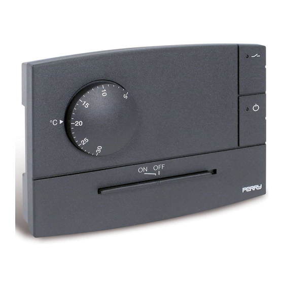
- Page 1 TERMOSTATI ELETTRONICI INSTALLAZIONE DA PARETE O DA SEMINCASSO SURFACE-MOUNTED OR SEMI FLUSH-MOUNTED ELECTRONIC THERMOSTATS THERMOSTATS ÉLECTRONIQUES POUR MONTAGE EN SAILLIE OU SEMI-ENCASTRÉ ELEKTRONISCHER THERMOSTAT FÜR WANDMONTAGE ODER EINGELASSENE INSTALLATION TERMOSTATOS ELECTRÓNICOS DE PARED O SEMIEMPOTRADO PE - DETENN500 07/18...
- Page 2 DATI TECNICI - ISTRUZIONI PER L’INSTALLAZIONE GB - English IT - Italiano Pagina 3 MODO D’IMPIEGO TECHNICAL DATA - INSTALLATION GUIDELINES EN - English Page 10 USER INSTRUCTIONS DONNÉES TECHNIQUES - NORMES D’INSTALLATION FR - Français Page 17 MODE D’EMPLOI TECHNISCHE DATEN - NORMEN FÜR DIE INSTALLATION DE - Deutsch Seite 24...
-
Page 3: Avvertenze Per La Sicurezza
AVVERTENZE PER LA SICUREZZA Si raccomanda di leggere attentamente le presenti istruzioni di installazione ed uso e conservarle per future consultazioni. Il costruttore si riserva la facoltà di introdurre tutte le modifiche tecniche e costruttive che riterrà necessarie senza obbligo di preavviso. - Page 4 Modello con: Modello con: Ingresso per comando remoto di riduzione della temperatura Ingresso per comando remoto di riduzione della temperatura LED rosso stato del relè LED rosso stato del relè (acceso = utenza attivata) (acceso = utenza attivata) LED rosso termostato in funzione (acceso = termoregolazione attivata) LED verde alimentazione (acceso = presenza di rete)
-
Page 5: Esempi Di Installazione
ESEMPI DI INSTALLAZIONE Importante: l'installazione ed il collegamento elettrico del dispositivo devono essere eseguiti solo da elettricista qualificato ed in conformità alle norme e leggi vigenti. Il costruttore non si assume alcuna responsabilità per quanto concerne l’impiego di prodotti che debbano seguire particolari norme di ambiente e/o installazione. -
Page 6: Installazione Del Termostato
INSTALLAZIONE DEL TERMOSTATO Modelli per installazione a SEMINCASSO Modelli per installazione a PARETE Per assicurare un corretto montaggio del termostato al supporto o alla base a parete, g l i s t e s s i n o n d e v o n o presentare incurvature dovute all’eccessivo serraggio delle viti di fissaggio nella scatola... -
Page 7: Collegamenti Elettrici
Importante: con forti carichi induttivi (pompe ed elettrovalvole) COLLEGAMENTI ELETTRICI si consiglia di collegare un filtro RC in parallelo al carico. disattivare la tensione di rete Collegare l’alimentazione di rete 230V~ ai morsetti: Collegamenti per la selezione remota della temperatura n°... - Page 8 Principio di funzionamento del comando a bordo (per modelli predisposti) o remoto di riduzione della temperatura Temperatura “ Comfort ” Contatto remoto aperto Temperatura “ Comfort ” Commutatore in posizione ON Temperatura “ Riduzione ” Contatto remoto chiuso Temperatura “ Riduzione ”...
- Page 9 LIMITAZIONE TEMPERATURA MASSIMA DELL’AMBIENTE E' possibile prefissare da 16 °C a 24 °C, con step di 2 °C, il massimo valore di temperatura impostabile. Fori per limitazione set di temperatura N.B.: il termostato viene fornito con il "disco range" preinstallato con il perno nel foro 16 °C neutro (nessuna limitazione di temperatura).
-
Page 10: Safety Precautions
SAFETY PRECAUTIONS Read this manual carefully before using the product as it provides important guidelines regarding safety, installation and use. The manual must be preserved with care for future reference. The manufacturer reserves the right to introduce any technical and/or constructive changes deemed necessary, with no prior notice. Before starting any operations on the device, disconnect the 230V~ mains power supply TECHNICAL DATA DATI TECNICI... - Page 11 Model with: Model with: Input for remote control temperature reduction Input for remote control temperature reduction Relay status red LED Relay status red LED (alight = load ON) (alight = load ON) Thermostat On red LED (alight = thermoregulation ON) Supply voltage green LED (alight = power ON)
-
Page 12: Installation Examples
INSTALLATION EXAMPLES Important: t he installation and electrica connections of devices and appliances must b e i m p l e m e n t e d b y p e r s o n w i t h electrotechnical expertise only and in conformity with current laws and regulations. -
Page 13: Thermostat Installation
THERMOSTAT INSTALLATION Models for SEMI FLUSH mounting Models for SURFACE mounting To ensure correct fitting of the thermostat to the support or surface-mounted base, make sure the latter are not distorted by overtightening of the fixing screws in the round or rectangular flush-mounted box. -
Page 14: Electrical Connections
IMPORTANT: for heavy inductive loads (pumps and solenoid ELECTRICAL CONNECTIONS valves) it is advisable to connect an RC filter in parallel with the Switch mains supply off load. Connect 230V ~ power supply to the terminals: Connections for the temperature "Reduction" remote n°... - Page 15 Working principle of the onboard (models where provided for) or remote temperature reduction control “ Comfort ” Temperatur Open remote c onta t “ Comfort ” Temperatur Switch in position ON “ R du ion ” Temperatur Closed remote contact “...
- Page 16 LIMITATION OF THE MAXIMUM ROOM TEMPERATURE It is possible to preset from 16 °C to 24 °C, with 2 °C step, the maximum temperature value. Holes for temperature setpoint limitation NB: the thermostat is supplied with the "range disc" preinstalled with pin in the neutral hole 16 °C (no temperature limitation).
-
Page 17: Mesures De Sécurité
MESURES DE SÉCURITÉ Il est recommandé de lire avec attention les présentes instructions d'installation et d'utilisation et de les conserver pour de futures consultations. Le fabricant se réserve la faculté d'apporter toutes les modifications techniques et de construction qu'il jugera nécessaires sans obligation de préavis. Avant d'effectuer tout travail sur le dispositif, couper l'alimentation du réseau 230V~. - Page 18 Modèle avec: Modèle avec: Entrée pour commande à distance de la réduction de la température Entrée pour commande à distance de la réduction de la température Rouge (DEL) état du relais Rouge (DEL) état du relais (allumée = charge activée) (allumée = charge activée) Rouge (DEL) thermostat en service (allumée = réglage thermique activé)
-
Page 19: Exemples D'installation
EXEMPLES D’INSTALLATION Important: 'installation et le branchement électrique des dispositifs et appareils doivent être effectués par un électricien qualifié et conformément aux normes et aux lois en vigueur. Le constructeur n'assume aucune responsabilité en ce qui concerne l'utilisation des produits qui doivent suivre des normes particulières concernant l'environnement et/ou l'installation. -
Page 20: Installation Du Thermostat
INSTALLATION DU THERMOSTAT Modèles pour montage SEMI-ENCASTRÉ Modèles pour montage EN SAILLIE Pour un montage correct du thermostat sur la plaque ou la base murale, celles-ci ne doivent pas être courbées à cause d'un serrage excessif des vis de fixation à la boîte r o n d e o u r e c t a n g u l a i r e encastrée dans le mur. -
Page 21: Branchements Electriques
IMPORTANT: en cas de fortes charges inductives (pompes et BRANCHEMENTS ELECTRIQUES électrovalves), il est conseillé de raccorder un filtre RC en Désactiver la tension du réseau parallèle à la charge. Brancher les fils d’alimentation 230V~ aux bornes: Connexions pour la commande à distance de "Réduction" n°... - Page 22 Principe de fonctionnement de la commande embarquée (modèles pré-équipés) ou à distance de réduction de la température Température “ Comfort ” Contact à distance ouvert Température “ Comfort ” position: ON Commutateur Température “ Réduction ” Contact à distance fermé Température “...
- Page 23 LIMITATION DE LA TEMPÉRATURE AMBIANTE MAXIMALE Il est possible de programmer la valeur maximum de température programmable de 16 °C à 24 °C avec des pas de 2 °C. Trous pour limiter la plage de température N.B.: le thermostat est livré avec un "disque gamme de température" pré-installé, son axe 16 °C se trouvant dans le trou neutre (aucune limite de température).
-
Page 24: Technische Daten
SICHERHEITSVORKEHRUNGEN Es wird empfohlen, die vorliegende Montage- und Gebrauchsanweisung aufmerksam durchzulesen und für spätere Fragen aufzubewahren. Der Hersteller behält sich das Recht vor, technische Modifikationen und Konstruktionsänderungen, die der Produktverbesserung dienen, ohne vorherige Ankündigung vorzunehmen. Vor der Ausführung jeglicher Arbeiten am Gerät ist die Netzversorgung 230 V~ zu unterbrechen TECHNISCHE DATEN DATI TECNICI DATI TECNICI... - Page 25 Modell mit: Modell mit: Eingang für Fernsteuerung zur Reduzierung der Temperatur Eingang für Fernsteuerung zur Reduzierung der Temperatur Rote LED Relaiszustands Rote LED Relaiszustands (leuchtet = Ladefunktion aktiviert) (leuchtet = Ladefunktion aktiviert) Rote LED-Anzeige Thermostatbetrieb (leuchtet = temperaturregelung aktiviert) Grüne LED Versorgungsspannung (leuchtet = Netzversorgung) Umschalter: ON = temperaturregelung aktiviert...
- Page 26 INSTALLATIONSBEISPIELE Die Installation und der elektrische Anschluß d e r G e r ä t e m u ß d u r c h n u r v o n Elektrofachkraft und in Übereinstimmung mit den geltenden Vorschriften und gesetzlichen Bestimmungen vorgenommen werden.
- Page 27 INSTALLATION DER GERÄTS Modelle für WANDMONTAGE Modelle für EINGELASSENE Installation Für die korrekte Montage des Thermostats auf der Halterung oder der Wandbasis dürfen sich dieselben nicht durch zu s t a r k e s Fe s t z i e h e n d e r Befestigungsschrauben auf dem runden oder rechteckigen Unterputzgehäuse verziehen.
-
Page 28: Elektrische Anschlüsse
HINWEIS: bei starken induktiven Lasten (Pumpen und ELEKTRISCHE ANSCHLÜSSE Elektroventile) wird empfohlen einen RC-Filter parallel zu Trennen sie das stromnetz ab schalten. Versorgungskabel (230 V~) an die klemmen angeschlossen: Anschlüsse für die Fernsteuerung der Temperatur - n° = Leitung "Reduzierung" (Modelle mit Vorrüstung) n°... - Page 29 Funktionsprinzip der Temperaturreduzierung auf dem Gerät (Modelle mit Vorrüstung) oder mit Fernsteuerung Temperatur “ omfort” onta kt Fernsteuerung offen Temperatur “Komfort” Umschalter: ON Temperatur “Reduzierung” onta kt Fernsteuerung geschlossen Temperatur “Reduzierung” Umschalter: Beispiele Geschlossen onta t Offen Offen Die Auswahl der Temperatur “Reduzierung” führt zu einer Verringerung von 4 °C in Bezug 24 °C auf den eingestellten Temperatursollwert.
- Page 30 BEGRENZUNG DER MAXIMALEN RAUMTEMPERATUR Der höchste einstellbare Temperaturwert kann in Schritten von 2 °C zwischen 16 und 24 °C Bohrungen für den Sollwert vorgegeben werden. der Temperaturbegrenzung Hinweis: der Thermostat wird mit der werkseitig eingebauten "Scheibe Temperaturbereich" 16 °C geliefert; der Stift steckt in der Bohrung des Nullleiters (keine Temperaturbegrenzung). 18 °C 20 °C Einstellung der Temperaturbegrenzung oder anschließende Änderung...
-
Page 31: Precauciones De Seguridad
PRECAUCIONES DE SEGURIDAD Se recomienda leer con atención las presentes instrucciones de instalación y uso, conservándolas para futuras consultas. El fabricante se reserva el derecho de realizar las modificaciones técnicas y de fabricación que considere oportunas, sin obligación de aviso previo. Antes de realizar cualquier trabajo en el dispositivo corte la alimentación de red de 230V~ DATOS TÉCNICOS Tensión de alimentación:... - Page 32 Modelo con: Modelo con: Entrada para mando remoto para la reducción de la temperatura Entrada para mando remoto para la reducción de la temperatura LED rojo de estado del relé LED rojo de estado del relé (encendido = carga activada) (encendido = carga activada) LED rojo termostato en funcionamiento (encendido = termorregulación activada)
-
Page 33: Ejemplos De Instalación
EJEMPLOS DE INSTALACIÓN La instalación y la conexión eléctrica de los dispositivo y equipos deben ser realizadas unicamente por electricistas especializados, de conformidad con las normas y leyes vigentes. El constructor no asume ninguna responsabilidad en lo concerniente al empleo de productos que deban seguir particulares normas ambientales y/o de instalación. -
Page 34: Instalación Del Termostato
INSTALACIÓN DEL TERMOSTATO Modelos para instalación de PARED Modelos para instalación SEMIEMPOTRADA Para asegurar un correcto montaje del termostato en el soporte o en la base de pared, estos no deben presentar curvaturas debidas al apriete excesivo de los tornillos de fijación de la caja redonda o rectangular empotrada en la pared. -
Page 35: Conexiones Eléctricas
Importante: si las cargas inductivas son fuertes (como en el CONEXIONES ELÉCTRICAS caso de las bombas y elettroválvulas) se aconseja conectar un Desactivar la tensión de red filtro RC en paralelo a la carga. Conecte los cables de alimentación 230V~ al borne: Conexiones para el mando a distancia de reducción de la n°... - Page 36 Principio de funcionamiento del mando de reducción de la temperatura instalado a bordo (modelos preparados) o a distancia Temperatura “ Co fort ” Contacto remoto abierto Temperatura “ Comfort ” Conmutador en posición: ON Temperatura “ Reducción ” Contacto remoto cerrado Temperatura “...
- Page 37 LÍMITE DE LA MÁXIMA TEMPERATURA AMBIENTE Puede prefijarse de 16 °C a 24 °C con incrementos de 2 °C, el máximo valor de temperatura que puede establecerse. Orificios para limitar la temperatura programada N.B.: el termostato posee un disco de rango preinstalado con el perno en el orificio neutro 16 °C (ninguna limitación de temperatura).
- Page 38 SMALTIMENTO DI VECCHI APPARECCHI ELETTRICI ED ELETTRONICI Questo simbolo sul prodotto o sul suo imballo indica che questo prodotto non può essere trattato come rifiuto domestico. Al contrario, dovrà essere portato ad un punto di raccolta determinato per il riciclaggio degli apparecchi elettrici ed elettronici, come ad esempio: - punti vendita, nel caso si acquisti un prodotto nuovo simile a quello da smaltire - punti di raccolta locali (centri di raccolta rifiuti, centri locali di riciclaggio, ecc...).
- Page 39 ENTSORGUNG VON GEBRAUCHTEN ELEKTRISCHER UND ELEKTRONISCHER GERÄTEN Dieses Symbol auf dem Produkt oder seiner Verpackung weist darauf hin, dass dieses Produkt nicht als normaler Haushaltsabfall zu behandeln ist, sondern an einer Annahmestelle für dal Recycling von elektrischen oder elektronischen Geräten abgegeben werden muss, wie zum Beispiel: - an den Verkaufsstellen, falls Sie ein ähnliches Neugerät kaufen.
- Page 40 Il costruttore si riserva la facoltà di introdurre tutte le modifiche tecniche e costruttive che riterrà necessarie senza obbligo di preavviso. The manufacturer reserves the right to make all technical and manufacturing modifications deemed necessary without prior notice. Le fabricant se réserve la faculté d’apporter, sans obligation de préavis, les modifications qu’il jugera nécessaires à...
Need help?
Do you have a question about the 1TPTE501B and is the answer not in the manual?
Questions and answers