Table of Contents
Advertisement
Available languages
Available languages
Quick Links
WALL MOUNTING ELECTRONIC DIGITAL THERMOSTAT
With LCD display and battery power supply - 3 V
THERMOSTAT ELECTRONIQUE DIGITAL POUR MONTAGE EN SAILLIE
Avec afficheur LCD et alimentation par batteries - 3 V
ELEKTRONISCHER DIGITAL RAUMTHERMOSTAT WANDMONTAGE
Mit LCD-display und Batteriebetrieb - 3 V
TERMOSTATO ELETTRONICO DIGITALE DA PARETE
Con display LCD e alimentazione a pile - 3 V
TERMOSTATO ELECTRONICO DIGITAL DE PARED
Con pantalla LCD y alimentación por pilas - 3V
lm - DETPNN003
04/03
Model with ON - Reduction - OFF switch
Modèle avec commutateur ON - Réduction - OFF
Modell mit Umschalter ON - Nachtbetrieb - OFF
Modello con commutatore ON - Riduzione - OFF
Modelo con conmutador ON - Reducción - OFF
Model with Winter - OFF - Summer switch
Modèle avec commutateur Hiver - OFF - Eté
Modell mit umschalter Winter - OFF - Sommer
Modello con commutatore Inverno - OFF - Estate
Modelo con conmutador Invierno - OFF - Verano
Advertisement
Table of Contents

Related Manuals for Perry 1TPTE400-B


Summary of Contents for Perry 1TPTE400-B
- Page 1 WALL MOUNTING ELECTRONIC DIGITAL THERMOSTAT With LCD display and battery power supply - 3 V THERMOSTAT ELECTRONIQUE DIGITAL POUR MONTAGE EN SAILLIE Avec afficheur LCD et alimentation par batteries - 3 V ELEKTRONISCHER DIGITAL RAUMTHERMOSTAT WANDMONTAGE Mit LCD-display und Batteriebetrieb - 3 V TERMOSTATO ELETTRONICO DIGITALE DA PARETE Con display LCD e alimentazione a pile - 3 V TERMOSTATO ELECTRONICO DIGITAL DE PARED...
- Page 2 TECHNICAL DATA - INSTALLATION GUIDELINES GB - English Page 3 USER INSTRUCTIONS DONNÉES TECHNIQUES - NORMES D’INSTALLATION Page 9 F - Français MODE D’EMPLOI TECHNISCHE DATEN - NORMEN FÜR DIE INSTALLATION D - Deutsch Seite 15 BEDIENUNGSANLEITUNG DATI TECNICI - ISTRUZIONI PER L’INSTALLAZIONE Pagina 21 I - Italiano MODO D’IMPIEGO...
-
Page 3: Technical Data
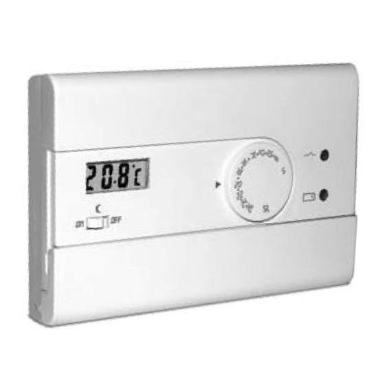
ENGLISH 1 - TECHNICAL DATA Supply voltage: N° 2 alkaline batteries 1,5V each type AAA (LR03) Type of action, disconnect and device: 1/ B / Electronic Type of output: Relay with changeover contact NO / COM / NC voltage free - max 8(2)A / 250 V 2 or 3 conductors Output connection (load): ire section at terminals:... - Page 4 2 - SIGNALS AND CONTROLS Battery low LED (brief flashes = battery low) Temperature display Room temperature display Load status LED (brief flashes = load ON) Temperature setting display Temperature setting knob The display normally shows the detected room tempe- rature.
- Page 5 3 - INSTALLATION GUIDELINES Dimensions Installation of thermostat: independent - fixed Wall mounting. Install the thermostat at a height of 1,5 m ÷ 1,7 m from the floor, far from heat sources, air vents, doors or win- dows and anything else that could affect its operation. h 1,5 m Important: installation and electrical connections of devi- ces and appliances must be carried out by skilled people...
-
Page 6: Electrical Connections
4 - FIXING BASE TO THE WALL Isolate the controlled appliance from the electrical power supply. Fix with screws the base of the thermostat to the back box (or to the wall), using the pairs of holes provided. - for round box (diam. 60mm) with claws - for round or square box (with screws) - for 3 spaces rectangular box (with screws) - knockouts allowing entry of wires (flexible only) -
Page 7: Inserting Or Replacing Batteries
6 - TEMPERATURE DIFFERENTIAL VALUE SETTING - t The thermostat operates in differential modes (ON-OFF) with a modifiable differential value (factory-set to 0,5 °C). Changing the differential: position the dip-switches, located on the back of the thermostat, for the required differential Dt = 0,3 °C Dt = 0,5 °C Dt = 0,7 °C... - Page 8 9 - LIMITATION OF THE MAXIMUM ROOM TEMPERATURE The maximum adjustable value of the temperature setting can be limited as Neutral follows: turn the knob to the 5 °C mark; then remove the knob (fig. A) extract the JUMPER from its housing (fig. B) Insert the JUMPER in the holes corresponding to the desired temperature (fig.
-
Page 9: Données Techniques
FRANÇAIS 1 - DONNÉES TECHNIQUES Tension d’alimentation: N° 2 piles alcalines 1,5V mini stylo type AAA (LR03) Type d’action, déconnexion et appareil: 1/ B / Electronique Type de sortie: A relais avec contact d’échange NO / COM / NF libre de potentiel - max 8(2)A / 250 V Connexion asservissement (charge): 2 ou 3 conducteurs min. - Page 10 2 - COMMANDES ET SIGNALISATIONS LED batterie déchargée (clignotements courts = batterie déchargée) Visualisation de la température - Visualisation température ambiante LED état de la charge (clignotements courts = charge activée) - Visualisation température en cours de paramétrage Manette de réglage de la température L’afficheur visualise normalement la température am- biante mesurée.
-
Page 11: Normes D'installation
3 - NORMES D’INSTALLATION Dimensions Installation du thermostat: indépendant - fixe En saillie. Installer le thermostat à 1,5 m ÷ 1,7 m. du sol, loin de sources de chaleur, de prises d’air, de portes ou de fenêtres et de tout ce qui peut agir sur le fonctionnement. h 1,5 m Important: l’installation et le branchement èlectrique des dispositifs et appareils doivent être effectués par du per-... -
Page 12: Branchements Electriques
4 - FIXATION DE LA BASE AU MUR Mettre le dispositif à commander hors tension. Fixer à vis la base du thermostat à la boîte à encastrer (ou au mur) en utilisant les paires de trous prévues à cet effet. - pour boîte ronde (diam. - Page 13 6 - IMPOSTATION DU VALEUR DU DIFFERENTIEL DE TEMPÉRATURE Le thermostat fonctionne en mode diffé- rentiel (ON-OFF) avec une valeur du dif- férentiel modifiable (fixèe en usine à 0,5 °C). Modification du différentiel: positionner les commutateurs multiples (dip-switch) à l’arrière du thermostat, pour la valeur Dt = 0,3 °C Dt = 0,5 °C Dt = 0,7 °C...
- Page 14 9 - LIMITATION DE LA TEMPÉRATURE AMBIANTE MAXIMALE Il est possible de limiter la valeur maximum de température en agissant comme Neutral suit: mettre la manette au niveau de 5 °C; sortir la manette (fig. A) extraire le CAVALIER de son logement (fig. B) insérer le CAVALIER dans les trous correspondants à...
-
Page 15: Technische Daten
DEUTSCH 1 - TECHNISCHE DATEN Versorgungsspannung: N. 2 Batterien Alkali-Stabbatterien Mod. AAA (LR03) 1,5 V Antrieb, Trennen der Verbindung und Gerät: 1/ B / Elektronisches Gerät Ausgang Relais mit unipolarem Weichenkontakt NO / COM / NC und potentialfrei 8(2)A / 250 V 2 oder 3 Leiter Anschluss des Verbrauchers (Last): Kabelquerschnitt für Klemmen... - Page 16 2 - LEISTUNGSMERKMALE LED Batterie entladen (LED blitzt = Batterie entladen Anzeige der Temperatur - Anzeige der Raumtemperatur LED Ladezustand (LED blitzt = Ladefunktion aktiviert) - Anzeige der eingestellten Temperatur Drehknopf für Temperatureinstellung Normalerweise zeigt das Display die gemessene Raum- temperatur an.
- Page 17 3 - NORMEN FÜR DIE INSTALLATION Abmessungen Installation der Geräts: unabhängig - fest Schiene. Bringen Sie den Thermostat möglichst in einer Höhe von 1,5 m ÷ 1,7 m, entfernt von Wärmequellen, Luftzufuhrgittern, Fenestern und Türen und weiteren den Betrieb des Gerätes beeinträchtigenden Gegenständen bzw.
-
Page 18: Elektrische Anschlüsse
4 - BEFESTIGUNG DER GRUNDPLATTE Trennen Sie die zu steuernde Vorrichtung vom Stromnetz ab. Befestigen Sie mit Schrauben die Grundplatte des Thermostats am Gehäuse (oder an der Wand) mittels der entsprechenden vorgegebenen Bohrungslöcher. - für rundes Gehäuse (Durchmesser 60 mm) für rundes oder rechteckiges Gehäuse mit Schrauben für rechteckiges Gehäuse (3 Plätze)mit Schrauben - Herausnehmbare Teile, die das Anklemmen der (ausschließlich... -
Page 19: Einsetzen Und Auswechseln Der Batterien
6 - EINSTELLUNG DES DIFFERENTIALWERTES - t Der Thermostat funktioniert in Differential- betrieb (ON-OFF) mit dem vorgegebenen Dfferentialwert 0,5 °C. Der Differentialwert kann verändert werden. Änderung des Differentialwerts: die auf der Rückseite des Thermostat Körpers Dt = 0,3 °C Dt = 0,5 °C Dt = 0,7 °C Dt = 0,9 °C gelegenen DIP-Schalter gemäß... - Page 20 9 - BEGRENZUNG DER MAXIMALEN RAUMTEMPERATUR Der für die Temperatureinstellung wählbare Höchstwert kann wie folgt eingestellt Neutralen werden: Stellen Sie den Drehknopf auf 5 °C. Dann nehmen Sie den Drehknopf ab. (Abb. A) den ÜBERBRÜCKUNGSDRAHT herausnehmen (Abb. B) den ÜBERBRÜCKUNGSDRAHT in die der gewünschten Temperatur entsprechenden Löcher einsetzen (Abb.
-
Page 21: Dati Tecnici
ITALIANO 1 - DATI TECNICI DATI TECNICI N. 2 pile alcaline Ministilo 1,5 V tipo AAA (LR03) Tensione di alimentazione: Tipo di azione, disconnessione ed apparecchio: 1/ B / Elettronico A relè con contatto in scambio NA / COM / NC Tipo di uscita: libero da potenziale - max 8(2)A / 250 V~ 2 o 3 conduttori... -
Page 22: Comandi E Segnalazioni
2 - COMANDI E SEGNALAZIONI LED batterie scariche (brevi lampeggi = batterie scariche) Visualizzazione della temperatura - Visualizzazione temperatura ambiente LED stato del carico (brevi lampeggi = carico attivato) - Visualizzazione temperatura in impostazione Normalmente il display visualizza la temperatura am- Manopola per impostazione temperatura biente rilevata. -
Page 23: Norme Per L'installazione
3 - NORME PER L’INSTALLAZIONE Dimensioni d’ingombro nstallazione del termostato: indipendente - fisso A parete. Installare il termostato a 1,5 m ÷ 1,7 m dal pavimento; lontano da fonti di calore, prese d’aria, porte o finestre e da quanto possa influenzarne il funzionamento. h 1,5 m Importante: l’installazione ed il collegamento elettrico dei dispositivi ed apparecchiature devono essere eseguiti da... -
Page 24: Collegamenti Elettrici
4 - FISSAGGIO DELLA BASE A PARETE Disattivare la tensione di alimentazione del dispositivo da comandare. Fissare con viti la base del termostato alla scatola incasso (o alla parete) utilizzando le apposite coppie di fori. - per scatola tonda (diam. 60 mm) con griffe - per scatola tonda o quadra (con viti) - per scatola rettangolare 3 posti (con viti) - aree asportabili per passaggio fili (solo flessibili) - Page 25 6 - IMPOSTAZIONE DEL VALORE DEL DIFFERENZIALE DI TEMPERATURA- t I l t e r m o s t a t o f u n z i o n a i n m o d o differenziale (ON-OFF) con il valore del differenziale modificabile (prefissato in fabbrica a 0,5°C).
- Page 26 9 - LIMITAZIONE TEMPERATURA MASSIMA DELL’AMBIENTE E’ possibile limitare il valore massimo regolabile del set di temperatura Neutro agendo come segue: portare la manopola in corrispondenza dei 5 °C; quindi estrarre la manopola (fig. A) estrarre il PONTICELLO dal suo alloggiamento (fig. B) inserire il PONTICELLO nei fori corrispondenti alla temperatura voluta (fig.
-
Page 27: Datos Técnicos
ESPANOL 1 - DATOS TÉCNICOS Tensión de alimentación: N. 2 pilas alcalinas de 1,5V mini mod. AAA (LR03) Tipo de acci ón, disconexión y aparato 1/ B / Electrónico Tipo de salida: Relé con contacto en intercambio NA / COM / NC libre de potencial - max 8(2)A / 250 V Conexión de los servicios (carga): 2 o 3 conductores... - Page 28 2 - SEÑALIZACIONES Y COMANDOS LED batería descargada Visualización de la temperatura (breves parpadeos = batería descargada) - Visualización de la temperatura ambiente LED estado de la carga (breves parpadeos = carga activada) - Visualización de la temperatura que se está programando Mando de regulación de la temperatura Normalmente en pantalla se visualza la temperatura ambiente detectada.
-
Page 29: Normas De Instalación
3 - NORMAS DE INSTALACIÓN Dimensiones Instalación del termostato: indipendente - fijo En superficie. Instalar el termostato a 1,5 m ÷ 1,7 m del suelo, lejos de fuentes de calor, respiraderos, puertas, ventana u otros elementos que puedan influir en el funcionamiento. h 1,5 m Importante: la instalación y la conexión eléctrica de los dispositivos y equipos deben ser realizadas por personal... -
Page 30: Conexiones Eléctricas
4 - FIJACIÓN DE LA BASE EN LA PARED Desactivar la tensión del dispositivo que se desea gobernar. Fijar y tornillos la base del termostato en la caja empotrada (o en la pared) utilizando los pares de orificios. - y ganchos si la caja es redonda (de 60 mm de diám.) - y tornillos si la caja es redonda o cuadrada - y tornillos si la caja es rectangular de 3 módulos - ares extraíbles para la entrada de los conductores (sólos flexibles) - Page 31 6 - PROGRAMACIÓN DEL VALOR DEL DIFERENCIAL DE TEMPERATURA - t EL termostato funciona de modo diferen- cial (ON-OFF). El valor del diferencial viene de fàbrica preestablecido en 0,5 °C. El valor puede modificarse. Modificación del diferencial: Posicionar los microinterruptores DIP situados en la Dt = 0,3 °C Dt = 0,5 °C Dt = 0,7 °C...
- Page 32 9 - LÍMITE DE LA MÁXIMA TEMPERATURA AMBIENTE Es posible limitar el valor máximo regulable para la temperatura de la siguiente Neutro manera: girar el mando asta los 5 °C; luego extraer el mando (fig. A) extraer el PUENTE del compartimento (fig. B) introducir el PUENTE en la posición de la temperatura deseada (fig.
- Page 33 NOTES - ANMERKUNGEN - NOTE - NOTAS...
- Page 34 NOTES - ANMERKUNGEN - NOTE - NOTAS...
- Page 35 The manufacturer reserves the right to make all technical and manufacturing modifications deemed necessary without prior notice. Le fabricant se réserve la faculté d’apporter, sans obligation de préavis, les modifications qu’il jugera nécessaires à la construction. Der Hersteller behält sich das Recht vor, notwendige technische Änderungen ohne Vorankündigung vorzunehmen.
Need help?
Do you have a question about the 1TPTE400-B and is the answer not in the manual?
Questions and answers