Tommy Gate 650 Series Replacement Instructions
Liftgate, power unit, motor, or tank replacement
Hide thumbs
Also See for 650 Series:
- Mounting instructions (6 pages) ,
- Owner's/operator's manual (20 pages)
Advertisement
Quick Links
Power Unit, Motor, or Tank Replacement Instructions-
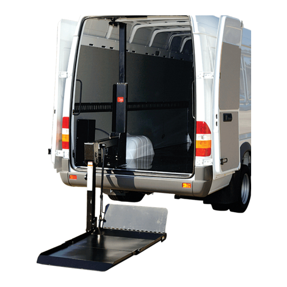
650 Series
The following instructions will aid you in replacing the power unit, motor, or tank on a 650 Series liftgate.
Removing the Power Unit
1. Raise and Store the platform in the latch.
2. Actuate the lowering function for five (5) seconds to relieve pressure in the system.
3. Disconnect the 4GA power cable from the positive side of the battery
or manually Trip the circuit breaker (Figure 2).
4. Remove the pump box cover by loosening four (4) hex head screws
or six (6) wing nuts (Figure 1).
5. Go to Replacing the Motor if replacing only the motor, otherwise proceed to next step.
6. Place a rag underneath the connection to absorb any
hydraulic oil that leaks when hose is loosened.
Caution: If the steps 7 and 8 are not performed properly, warranty will not be awarded for pulled threads.
7. Loosen elbow jam nut. While attempting to loosen the jam nut with an open end wrench,
hold the elbow in place using another open end wrench (Figure 3).
8. Disconnect hose to elbow connection. While attempting to loosen the hose with an open end wrench,
hold the elbow in place with another open end wrench (Figure 4).
9. Raise the disconnected hose end above the cylinder as soon as possible to minimize oil leakage.
10. Position the disconnected hose end in a location that is above the cylinder until hose is reconnected.
DPN: 095191
3
21-
"
4
Figure 3: Jam nut.
Page 1 of 4
19"
(6) Wing Nut
(3 per side)
Figure 1: Pump box cover fastener locations.
Manual Disconnect
Button
Figure 2: Circuit breaker.
Wrench
Jam nut
(tight)
Elbow
Wrench
Figure 4: Hose connection.
Rev 1
(4) Hex Screw
(2 per side)
Circuit
Breaker
Jam nut (loose)
Elbow
Wrench
Hose Hex Fitting
1-5-16
Advertisement

Related Manuals for Tommy Gate 650 Series


Summary of Contents for Tommy Gate 650 Series
- Page 1 Power Unit, Motor, or Tank Replacement Instructions- 650 Series The following instructions will aid you in replacing the power unit, motor, or tank on a 650 Series liftgate. Removing the Power Unit 1. Raise and Store the platform in the latch.
- Page 2 Power Unit, Motor, or Tank Replacement Instructions- 650 Series Removing the Power Unit (continued) 11. Remove the common ground bolt holding the 18GA black wire and the 4GA ground cable to the power unit housing (Figure 5). Note: Keep the common ground bolt for use when installing the new power unit.
- Page 3 Power Unit, Motor, or Tank Replacement Instructions- 650 Series Motor Cable Replacing the Motor 1. Disconnect the 4GA motor cable from the motor (Figure 6). Hose Clamp "Raise" Solenoid 2. Remove the hose clamp and "raise" solenoid from the moto r .
- Page 4 Power Unit, Motor, or Tank Replacement Instructions- 650 Series Reinstalling the Power Unit 1. Position the "raise" solenoid, hose clamp, and motor cable in the position indicated for your pump box design (Figure 7 or 8). 2. Install the power unit in the pump box with two 5/16" hex bolts.
Need help?
Do you have a question about the 650 Series and is the answer not in the manual?
Questions and answers