Table of Contents
Advertisement
Quick Links
Advertisement
Table of Contents

Related Manuals for Smartswitch TD-4000


Summary of Contents for Smartswitch TD-4000
- Page 1 SMARTSWITCH TD-4000 Tank Monitor Ver 8.4 Installation Manual...
- Page 2 Data Retention 50 years (without power) Outputs The TD-4000 has two (open collector) outputs, which can be used to turn a relay ON or OFF. These outputs can be used to control pumps e.g. Black discharge pump, or output 2 (only) can be programmed to activate a relay when the Black tank reaches the set alarm point to disable the toilet.
- Page 3 Pump 1 Pump 2 negative positive Relay Relay TD-4000 Pump Circuit Connection To Blue or White wire on the TD-4000 Relay Blue = Output 1 BATTERY White = Output 2 TO PUMP Disable Toilet Circuit Connection NOTE: Output 2 ONLY...
- Page 4 Connector Wiring Back View Model Serial No : D.O.M Input 4 Input 3 Input 2 Input 1 Signal Signal Signal Signal Connector Wiring For Ultra-Sonic Sender Connector Wiring SM-180 Adaptor Gnd = Black on Ultra-Sonic Sensor Gnd = Black on SM-180 Adaptor Signal In = Green on Ultra-Sonic Sensor Signal In = Yellow on SM-180 Adaptor + 12 vdc Out = Red on Ultra-Sonic Sensor...
-
Page 5: Display Functions
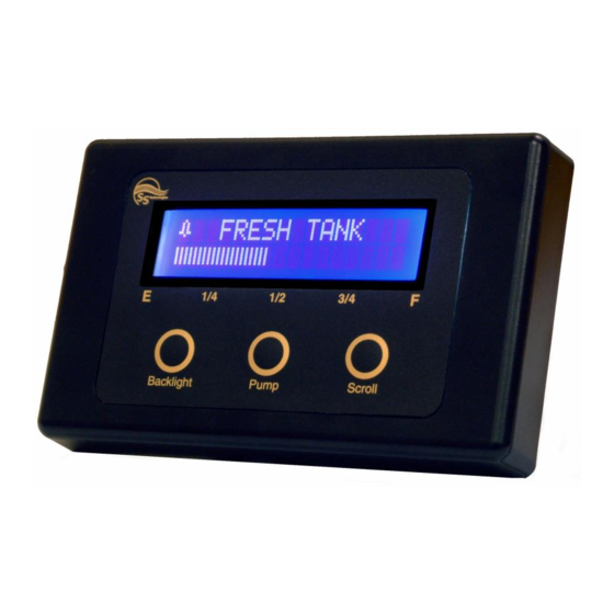
Back View Model Serial No : D.O.M Inputs Display Functions Alarm Tank Text Pump Port Fuel 240 Lts 62 % Backlight Pump Scroll Display Mode 1 Display Mode 2 This system has 2 display modes. See point 3 on page 10 - Operating Instructions to change. -
Page 6: Programming Instructions
Programming Instructions NOTE: Program Input & Calibrate must be preformed for each tank Step 1: Placing the unit in Program Mode Press and hold down the Backlight key now press and hold the Scroll key. Hold together for 3 seconds. SET-UP MENU PROGRAM INPUT... -
Page 7: Step 6: Audible Alarm
Step 4: Selecting Type The display will now show: Grey Water < INPUT TYPE > Use the Scroll or Backlight key to scroll through the various Input Type’s e.g. Grey Water, Black Water, Fresh Water, Fuel etc. Press the Pump key once the appropriate tank type has been found. Note: The tank type only sets where the alarm point starts and the pump default start or stop points. -
Page 8: Step 7: Tank Volume
Set Outputs The TD-4000 has two outputs and can be associated with any of the inputs. To set up this feature, scroll down to “Set Output” (in the Set-Up Menu) and press the Pump key. The display will now show:... - Page 9 (also see Pump Start / Stop: page 10) The TD-4000 has two Pump Output controls and works as follows: If used for Black or Grey you can turn it ON and OFF manually. If the pump is ON will turn OFF automatically when the tank is empty or at the programmed Pump Stop Point.
- Page 10 Pump Start / Stop: Day Tank: If a tank has been set as a Day Tank in the Tank TYPE set-up then this feature allows you to set when the transfer pump will automatically be turned On and Off. This can be set up by selecting the “Pump Start/ Stop” option from the Set-Up Menu and selecting the tank you wish to set this up on.
- Page 11 External Alarm : Using Output 2 (white ) for external alarm: Note: External alarm can be used for both low and high or just high. Step 1: From the Set-Up Menu scroll down to “External Alarm” then press the Pump key. The display will now show: Tank Name ? Select Input...
- Page 12 Transfer Fuel Feature: This feature allows for the pump output to have both low and high stop points. Step 1: When programming a tank and the INPUT TYPE screen is displayed. The display will now show: Transfer Fuel < INPUT TYPE >...
- Page 13 Scroll key until “Exit Menu” is displayed, then press the Pump key. This will save all associated data that has been set and take the system out of Set-Up mode and into Monitoring mode. The TD-4000 is now ready for use! Operating Instructions: 1/ Pressing the Backlight key will turn the backlight ON, press again to turn OFF.
-
Page 14: Sensor Installation
PLEASE NOTE: For sensor Model SEN-250 The Maximum Tank Height is 2.5 Meter The maximum surge and safe pressure is 28psi. For more information see “Calibration Tips & Tricks” on our web site www.smartswitch.co.nz Mounting Adaptors Available: A range of mounting adaptors are available which includes flat sidewall, top mount, 1.5” pipe, 2” pipe, 3” pipe and drain valve. - Page 15 Sensor Programming Instructions Placing the unit in Calibrate Mode Press and hold down the Backlight key now press and hold the Scroll key. Hold together for 3 seconds. This will bring you to the Set-Up Menu. SET-UP MENU PROGRAM INPUT PROGRAM INPUT CALIBRATE SET ALARM...
- Page 16 Once back at the Set-Up Menu repeat this process. This must be repeated for all additional Inputs. If no fluid is added the display will show: Value Not Larger Please Try Again For more information see “Calibration Tips & Tricks” on our web site www.smartswitch.co.nz...
- Page 17 5 Point Calibration: (Bottom, ¼, ½, ¾ & Top) Tank High Point 3/4 Point Half Point 1/4 Point Low Point The display will show: Set Empty Point Input = ?.?? v Voltage from Sensor (see table 1 page 19) Fill the tank to the required TANK LOW LEVEL, minimum suggested is liquid just covering the sensor. Wait for approx.
- Page 18 Value Not Larger Please Try Again For more information see “Calibration Tips & Tricks” on our web site www.smartswitch.co.nz If Ultra-Sonic is selected: the display will show “ Calibration Finished “ and the system will return to the Set- Up Menu. This is because the Ultra-Sonic sensor is to be pre-calibrated with its own hardware/software.
- Page 19 These voltages will be displayed during the calibration setup. Reason: Should the TD-4000 ever need to be replaced all tanks will need to be re-calibrated, but if table 1 has been filled out then creating these input voltages can be done without even the tank sender connected, making the process very simple.
- Page 20 © All technologies, design and Intellectual property is owned by Penguin Electronics Ltd Po Box 272, Waikanae. NZ Phone 0064-4-293-4201 Fax 0064-4-293-4201 Email: info@smartswitch.co.nz Web: www.smartswitch.co.nz...
Need help?
Do you have a question about the TD-4000 and is the answer not in the manual?
Questions and answers