Table of Contents
Advertisement
Quick Links
Advertisement
Table of Contents

Related Manuals for Smartswitch TC-8000


Summary of Contents for Smartswitch TC-8000
- Page 1 SMARTSWITCH TC-8000 Tank Monitor/Controller Installation Manual...
-
Page 2: Table Of Contents
Table of Contents Introduction System Overview Wiring Block Diagram System Layout Wiring Diagram (HT-100 & HB-200) Wiring Diagram (HT-100/P & HB-200/P) Product Photos Installation Steps Mounting Instructions Sensor Installation Sensor Programming Instructions Sensor Programming Instructions (cont.) Setting Rotary Switch (network address) Seacock Interlock Switch Installation Pump Current Sensing Programming Instructions... -
Page 3: Introduction
Introduction Thank you for purchasing the TC-8000 Holding Tank Controller. Smartswitch is very proud to be able to provide this product to you. The Smartswitch Research and Development Team has spent considerable time and effort in developing, designing and producing this system specifically for the marine environment. -
Page 4: System Overview
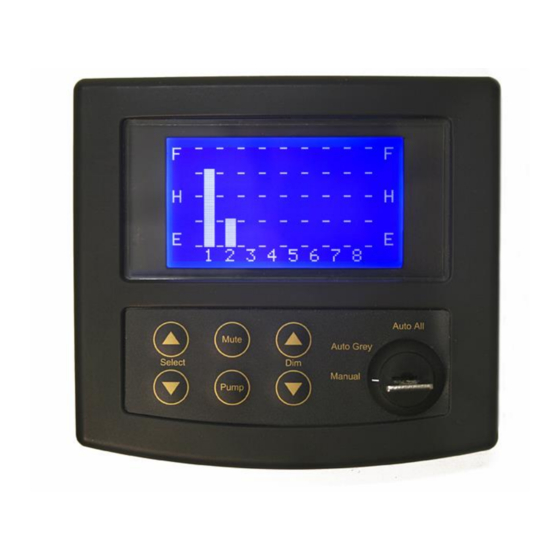
System Overview TC-8000 Master Display Unit (MDU) Provides the following functions: • full control from one central location on your boat • visual indication of tank level (bar graph or lts / gals & percentage) • visual indication of seacock position & pump status •... -
Page 5: Wiring Block Diagram
Wiring Block Diagram Black Battery Battery negative positive Display Unit Display Unit TC-8000 RD-800 White = Net – To next device Blue = Net + HT-100/P or HT-100 or HB-200/P (IOU) HB-200 (IOU) White=Net - White=Net - Blue=Net + Blue=Net +... - Page 6 Eight Channel Holding Tank Controller System Layout for Model TC-8000 Any Device can sit Anywhere on this Two Core Bus cable. Any combination of HT-100/P, HB-200/P and or HT-100, HB-200 (up to eight) can be connected, plus any number of repeater display units - Model RD-800.
-
Page 7: Wiring Diagram (Ht-100 & Hb-200)
Wiring Diagram for Model HT-100 Rotary Switch Program Button Tank sensor Net - Network Cable Net + Relay Wiring Diagram for Model HB-200 Rotary Switch Program Button Sensor In + 5 vdc Net - Network Net + Relay Battery - Battery + Wiring For Ultra-Sonic Sender Wiring For Pressure Sender SEN-B300... - Page 8 Wiring Diagram for Model HT-100/P If no Seacock Interlock Switch is used then place a jumper between Link and V/In1 (see page 14) Rotary Switch V/ln2 V/ln1 V/Out Link Net - Network Cable Net + Program Button Relay One Relay Two Tank sensor Pump positive...
- Page 9 HB-200 Input/Output Unit Program Button Rotary Switch HT-100/P or HB-200/P Input/Output Unit Program Button Rotary Switch SEN-100/250 Plug Connection Notch for Sensor wire in case...
-
Page 10: Installation Steps
Installation Steps Step 1: Install and connect the Master Display Unit. Step 2: Install, connect and calibrate the tank sensors. Step 3: Install and connect the I/O units (HT-100, HB-200 or HT-100/P, HB-200/P). Step 4: Set-up Rotary Switches. Step 5: Seacock Interlock Switch or Jumper. -
Page 11: Sensor Installation
Pilot Holes Sensor Installation If the Smartswitch pressure sensor is being fitted see pages 10, 11 and 12. PLEASE NOTE: If a charcoal filter is fitted to the Black tank see Special Pump (page 19) If the Ultra-Sonic sensor is being fitted see page 12. - Page 12 The maximum surge and safe pressure is 28psi. For more information see “Calibration Tips & Tricks” on our web site www.smartswitch.co.nz Mounting Adaptors Available: A range of mounting adaptors are available which include flat sidewall, top mount, 1.5” pipe, 2” pipe, 3” pipe and drain valve.
-
Page 13: Sensor Programming Instructions
Sensor Programming Instructions Two different methods of tank programming are available if using the pressure sensor: 2 Point Calibration: sets tank low and tank high points which can only be used if the tank is a regular size and shape. 5 Point Calibration: sets tank low, tank quarter, tank half, tank three quarters and tank full points, offering more accuracy if the tank is an irregular size and shape. - Page 14 You will see both LED’S flashing, please wait (approx 20 seconds) for the LED’S to stop flashing, the slave receiver now has the same calibration setting as the master transmitter. For more information see “Calibration Tips & Tricks” on our web site www.smartswitch.co.nz Ultra-Sonic Sensor : If using the Ultra-Sonic sensor turn the Rotary Switch to position 1 Press and hold down the Program Button for 3 seconds, the LED will flash 4 times and turn off.
-
Page 15: Setting Rotary Switch (Network Address)
Setting Rotary Switch (Network Address) Each Input/Output Unit (HT-100, HB-200 or HT-100/P, HB-200/P) on the network must have the Rotary Switch set to a unique number (from 2 to 9). NO two devices may share the same Rotary Switch number. The Rotary Switch is situated inside the Box of the HT-100/P and HB/200P Input/Output Unit and on the outside of the case on the HT-100 and HB-200 (see diagrams below and page 7 for position). -
Page 16: Seacock Interlock Switch Installation
Seacock Interlock Switch Installation Important: The HT-100/P and the HB-200/P provide for an interlock with a seacock valve to prevent the pump from starting in the event the seacock valve is closed. In the event there is no interlock contact on the seacock, the following procedure MUST be followed to allow the pump to operate in either manual or automatic mode. -
Page 17: Pump Current Sensing
Pump Current Sensing The HT-100/P & HB-200/P are equipped with special current sensing circuitry to detect if after a pump is turned on, it is in fact running. If a pump is turned on, either Manually or Automatically, and the pump fails to start due to short or open circuit, the pump icon for that tank will flash and the alarm will sound indicating a fault. -
Page 18: Programming Instructions
Programming Instructions Step 1: Placing the unit in Program Mode Press and hold down the Mute & Select Up keys together for 3 seconds. This will bring you to the Set-Up Menu and place the unit in program mode. SET-UP MENU PROGRAM TANK SUB MENU... - Page 19 Step 4: Selecting Tank Type The display will now show: Grey=1 Black=2 Fuel=4 Water=3 Select TankType Use Select Keys Push MUTE To Enter Use the Select Up or Down key to scroll through the tank various types (note this is not the tank name, it is the tank type).
- Page 20 Erasing Tanks: A tanks data may be completely erased. From the Set-Up Menu scroll to ERASE TANK and press the Mute key. The display will now show: GREY TANK Select Switch Push MUTE To Enter Push PUMP To EXIT Use the Select Up or Down key to scroll through the Switch numbers to the tank that requires erasing. Once the tank is displayed press the Mute key.
- Page 21 From the Set-Up Menu scroll down to EXIT MENU and press the Mute key. This will save all associated data that has been set and take the system out of program mode and into monitoring mode. The TC-8000 is now ready for use! Sub Menu: MENU SET PUMP POINT’S...
- Page 22 The display will now show: Set Pump Off Point Note: the arrow is the on point marker which shows where the pump Use Select Keys on point was set. Push MUTE To Enter Use the Select Up or Down key to move the Pump Off point to the desired level. Press the Mute key to set this as the Pump Off point and return you to the main menu.
- Page 23 Special Pump: If you are using a pressure sensor under the following conditions you will need to use this feature: 1. Black tank has a charcoal filter fitted** 2. Pressure sensor is located in the discharge pipe or any location where turbulence is likely during the pumping operation **Explanation: When the pump is turned on liquid is removed from the tank quicker than air can replace it, due to the constrictive nature of the air filter.
-
Page 24: Operating Instructions
Operating Instructions Keyboard: The Select Up and Down allows for scrolling between tanks. The Mute key mutes the alarm. The Pump key turns the pump on and off (see details below). Dim Up and Down adjusts the display contrast. The Grey and Black tanks have three Modes of operation Key Switch = Manual Mode: When any tank programmed as either Grey or Black reaches the programmed high-level point and the alarm is ON, the alarm will activate and show a flashing bell beside the tank icon. - Page 25 Fresh Tanks: The alarm will turn ON if the tank reaches the programmed low-level value and OFF when the tank has been filled by three bars. Pump Output (HT-100/P & HB-200/P only) The Pump Output will automatically turn ON if the tank is equal to or greater than the programmed pump ON value. The Pump Output will turn OFF when the tank is equal to or less than the programmed pump OFF value.
- Page 26 Should a programmed tank either lose communication, or power, the tank level indicator will display “----------COMMS FAULT-----------“. The tank level indicator will resume normal operation once the problem has been rectified. TC-8000 Wiring Connections Red = Battery + Black = Battery –...
- Page 27 This Calibration method applies to I/O Units manufactured before 01/06/2009 2 Point Calibration: Turn Rotary Switch on the I/O Box to position 0 Fill the tank to the required TANK LOW LEVEL, minimum suggested is liquid just covering the sensor. Wait for approx.
-
Page 28: Electrical Specifications
Electrical Specifications TC-8000 Supply Voltage 12 to 32 Volts DC (Auto-sensing) Quiescent Current 0.02 Amps Data Retention 50 years (without power) Electrical Specifications RD-800 Supply Voltage 12 to 32 Volts DC (Auto-sensing) Quiescent Current 0.03 Amps Data Retention 50 years (without power) Electrical Specifications HT-100 &... - Page 29 © All technologies, design and Intellectual property is owned by Penguin Electronics Ltd Po Box 272, Waikanae. NZ Phone 0064-4-293-4201 Fax 0064-4-293-4201 Email: info@smartswitch.co.nz Web: www.smartswitch.co.nz...
Need help?
Do you have a question about the TC-8000 and is the answer not in the manual?
Questions and answers