Table of Contents
Advertisement
Advertisement
Table of Contents

Related Manuals for Keyestudio EASY PLUG Ultimate Starter Kit


Summary of Contents for Keyestudio EASY PLUG Ultimate Starter Kit
- Page 1 EASY PLUG Ultimate Starter Kit For Arduino STEM EDU www.keyestudio.com...
-
Page 2: Table Of Contents
CONTENT 1. Kit Description ..............................1 2. Kit List ................................1 3. Getting Started with Mixly ..........................6 1) Introduction for Mixly ..........................6 2) Interface Functions of Mixly ......................... 6 2.1. System Functions ........................6 2.2. In/Out Block ..........................9 2.3. - Page 3 Project 20: What’s the temperature ....................215 Project 21: What time is it? ........................224 Project 22: I receive a signal ........................ 227 6. Resources ..............................234 7. Our Tutorial ..............................235 8. About keyestudio ............................235 9. Customer Service ............................236...
-
Page 4: Kit Description
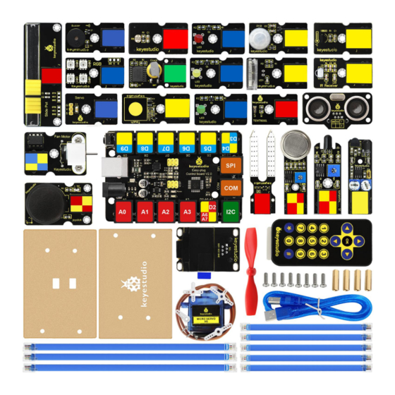
1. Kit Description The keyestudio EASY PLUG ultimate starter kit is based on Mixly blocks coding, very easy to use and flexible. This kit includes everything you need to complete Mixly projects that will teach you how to control and read external sensors and displays, sound control, learn Mixly Blocks programming, and much more. - Page 5 EASY plug Yellow LED Module EASY plug Red LED Module EASY plug Passive Buzzer Module EASY plug Photocell Sensor EASY plug Soil Humidity Sensor EASY plug Analog Gas Sensor EASY plug TEMT6000 Ambient Light Sensor EASY plug slide potentiometer module...
- Page 6 EASY plug Capacitive Touch Sensor EASY plug Knock Sensor EASY plug Flame Sensor Module EASY plug PIR Motion Sensor EASY plug DS18B20 Temperature Sensor EASY plug IR Receiver Module EASY plug Infrared Obstacle Detector Sensor EASY plug DS3231 Clock Module EASY plug Joystick Module...
- Page 7 EASY plug SR01 Ultrasonic Module EASY plug OLED Module EASY plug L9110 Fan Motor Module EASY plug Servo Module Keyestudio 9G blue Micro Servo 90° EASY plug 2812 2x2 full-color RGB Module 200mm blue RJ11 cable 300mm blue RJ11 cable...
- Page 8 USB cable...
-
Page 9: Getting Started With Mixly
3.Getting Started with Mixly 1) Introduction for Mixly Mixly is a free open-source graphical Arduino programming software, based on Google’s Blockly graphical programming framework, and developed by Mixly Team@ BNU. It is a free open-source graphical programming tool for creative electronic development; a complete support ecosystem for creative e-education;... - Page 11 Some common functions: Through this interface, you can complete the code compile、upload、save and manage. It support four remove methods: drag it left out code window, or drag to Recycle Bin, delete key, or right-click to delete block. It supports four languages: English、Español (Spanish)、中文简体(Chinese Simplified)、中文繁体 (Chinese Traditional).
-
Page 12: In/Out Block
2.2. In/Out Block... - Page 13 BLOCK ICON DEFINITION Returns HIGH or LOW voltage Write digital value to a specific Port. Digital Output: set the HIGH or LOW output for IO pins Returns a digital value of a specific Port. Digital IO Read Pin, generally used to read the HIGH or LOW level detected by Digital sensor Write analog value between 2 and 255 to a specific Port.
- Page 14 Returns value between 0 and 1023 of a specific Port. Analog IO Read Pin, generally used to read the Analog value detected by Analog sensor. External Interrupts function, with three trigger interrupt modes RISING, FALLING, CHANGE. Detachs interrupt to a specific Port. Turn off the given interrupt function.
- Page 15 Read the continuous time of HIGH or LOW pulse from IO pins ( generally used for ultrasonic ranging) Read a pulse (either HIGH or LOW) on a pin within a time set in timeout. Set the ShiftOut data pin, clock pin. Output the data needed from the bitOrder MSBFIRST or LSBFIRST (Most Significant Bit First, or, Least Significant Bit First).
- Page 16 For example: Connect your Arduino Uno board, then follow the steps below to light the Pin13 led on Arduino UNO.
-
Page 17: Control Block
2.3. Control Block... - Page 18 BLOCK ICON DEFINITION Initialization (run only once) End the program, means the program will stop running when use this block. Delay function, click to select ms or us (pause the program for the amount of time (in milliseconds) specified as parameter. There are 1000 milliseconds in a second.)
- Page 19 if_do function (first evaluate a value be true or false, if a value is true, then do some statement. You can click the blue gear icon to select the else if block or else block.) switch function. You can click the blue gear icon to select the case block or default block.
- Page 20 A while loop statement. break function, used to exit from the containing loop. millis() function, returns the system running time since the program started. (The unit can be ms (milliseconds) or μs (microsecond)).
- Page 21 Timer interrupt function, that is, set a trigger interrupt for the amount of time (in milliseconds) specified as parameter. Timer interrupt start block Timer interrupt stop block...
- Page 22 For example: Compile and upload the program below to your Arduino board, you should see Pin13 LED on Arduino UNO continue to flash.(with an interval of 1s, equal to 1000ms)
-
Page 23: Math Block
2.4. Math Block... - Page 24 BLOCK ICON DEFINITION A number Click to select the Arithmetic Operators: +(addition); -(subtraction); x (Multiplication); ÷ (division); % (remainder); ^ (bitwise xor) Click to select the & (bitwise end); l (bitwise or); << (bitshift left); >> (bitshift right)
- Page 25 Click to select the sin; cos; tan; asin; acos; atan; ln; log10; e^; 10^; ++ (increment) ; -- (decrement) Click to select the Round; Ceil; Floor; abs; sq; sqrt Round: Returns the integer part a number using around. Ceil: Returns the integer part a number using ceil.
- Page 26 If select the max, returns the larger number; if select the min, returns the smaller number. Initialize the random seed Return a random integer between the two specified limits, inclusive. Constrain a number to be between the specified limits (inclusive). (generally used to constrain an analog value read from sensor)
- Page 27 Map a number from the first interval to the second interval. (For instance, potentiometer-controlled servo, map the range of potentiometer (0, 1023) to the angle of servo (0, 180)).
-
Page 28: Text Block
2.5. Text Block... - Page 29 BLOCK ICON DEFINITION character string: a letter, word, or line of text. A character Creates a piece of text by joining together two piece of text. ( Here Hello join Mixly equals HelloMixly) Converts a string into an integer or an float. Returns the char corresponding to an ASCII code (Decimal number 97 corresponding to a)
- Page 30 Returns the ASCII code corresponding to a char. Converts a number into a string. Calculates the length of a string Output the char of a string (the char at 0 of hello is h) The first string equals or startsWith or endsWith the second string, returns 1, otherwise returns 0.
-
Page 31: List Block
2.6. List Block... - Page 32 BLOCK ICON DEFINITION Create a list with any number of items Creats a list from a text. (int mylist [ ]={0,0,0};) Returns the length of a list...
- Page 33 Returns the value of at the specified position in a list. Sets the value of at the specified position in a list. Set the first item in mylist to another item.
-
Page 34: Logic Block
2.7. Logic Block... - Page 35 BLOCK ICON DEFINITION logic comparision =: Return true if both inputs equal each other. ≠ : Return true if both inputs are not equal to each other. <: Return true if the first input is smaller than the second input. ≤...
- Page 36 and: Return true if both inputs are true; or: Return true if at least one of the inputs is true Returns true if the input is false. Returns false if the input is true. Returns either true or false. Returns null If the first number is true, the second number is returned, otherwise the third number.
-
Page 37: Variable Block
2.8. Variable Block... - Page 38 BLOCK ICON DEFINITION Declare and initialize a variable. Click to select int, long, float, boolean, byte, char, string Define the data types For example: LED breath You need an Arduino Uno and one LED module. Connect the control pin of LED module to Pin 3 of Uno board (or other pins with “~”,that is, those pins can output PWM signal).
-
Page 40: Serialport Block
2.9. SerialPort Block... - Page 41 BLOCK ICON DEFINITION Set the serial buad rate to 9600 Write the specified number, text or other value. Print the specified number, text or other value on monitor. Print the specified number, text or other value on newline of monitor.
- Page 42 Print the specified number in hexademical format on newline of monitor. If the serial port is available, it returns true, otherwise returns false. (generally used in Bluetooth communication) Returns a string in serial port A string read from serial port to a string variable, pause until read the specified character.
- Page 43 Wait for the output data completed Set the software serial port (call this function if need to use several serial ports) Event function trigger by serial port data, that is, serial port is ready to call this function. (equal to an interrupt function) For example: serial communication Done uploading the code, open the Arduino monitor, then enter a “hello”...
-
Page 46: Communicate Block
2.10. Communicate Block... - Page 47 BLOCK ICON DEFINITION Do something when receiving infrared signals. Sends infrared signals of the specified types. IR transmitter sends the data, here use the libraries, only PIN3 port.
- Page 48 Enable IR decoding Print the Infrared signal in RAW types when receiving Sends RAW infrared signals (set the pin number, list, length of list and IR frequency) For example: You need an Arduino Uno board, an IR receiver module and an IR remote control. Connect the signal pin of IR receiver to Digital pin 3 of Uno board, then upload the code and open the monitor.
-
Page 50: Sensor Block
2.11. Sensor Block... - Page 51 BLOCK ICON DEFINITION Set the Trig and Echo pin of ultrasonic sensor. Returns the distance of ultrasonic sensor measured. (unit: cm) Set the control pin of DHT11 temperature and humidity sensor. Returns the temperature or humidity of DHT 11 sensor measured. Set the pin of digital temperature sensor DS18B20.
- Page 52 For example: ultrasonic ranging Connect the Trig pin of ultrasonic sensor to Digital 1 of Uno, Echo pin to D2, then upload the code and open the monitor, you should see the distance value, updating once per 100ms.
-
Page 53: Actuator Block
2.12. Actuator Block... - Page 54 BLOCK ICON DEFINITION Sets the servo pin; Moves between 0-180 degree; Delay time for servo to rotate. Returns that degree with the last servo move. Read the degree of servo connected to IO pin set Set the pin and specified frequency for buzzer to play sound.
- Page 55 For example: Connect the signal end of servo to Digital 0 of Uno, then upload the code below, servo will rotate 90 degrees. Note: Delay 100ms is the time required for servo to move.
-
Page 56: Monitor Block
2.13. Monitor Block... - Page 57 BLOCK ICON DEFINITION Set the IIC LCD1602 address Input the value on LCD line 1 and line 2 from left to right. Set the row and column of LCD to print the char Clear the LCD screen Set the control pin and the number of RGB light.
- Page 58 Set the RGB light pin, light number and brightness Set the control pin, light number and color. (click to select the color) Clear the data, namely turn off digital display Four-digit display, displaying abcd. Turn on or off the digitdisplay (here turn on the first digitdisplay)
- Page 59 For example: Separately connect the SDA (A4) and SCL (A5) of Arduino Uno to SDA and SCL pins of IIC LCD1602, then set the address of your LCD1602 screen, the LCD address we used here is 0x27. Then upload the code, LCD screen has two lines, you should see the line 1 print HELLO, and line 2 print 123456789.
-
Page 60: Functions Block
2.14. Functions Block... - Page 61 BLOCK ICON DEFINITION Creates a function with no output. Click the blue icon to set the procedure parameter. (no return value) Creates a function with an output. Click the blue icon to set the procedure parameter. (with return value and can set the data types)
- Page 62 If a value is true, then return a second value. For example: Below is an example code for line tracking car. We use three tracking modules (left to D6, middle to D7, right to D8). of course you need a tracking car to test it. First edit the forward, backward, turn left, turn right and stop into functions block.
-
Page 65: Installing Arduino Software
4.Installing Arduino Software When you get the control board, first you should install the Arduino software and driver. We usually use the software Arduino 1.5.6 version. You can download it from the link below: https://www.arduino.cc/en/Main/OldSoftwareReleases#1.5.x Or you can browse the ARDUINO website to download the latest version from this link, https://www.arduino.cc, pop up the following interface. - Page 66 Click DOWNLOADS, it will appear the latest software version of ARDUINO 1.8.5 shown as below. In this software page, on the right side you can see the version of development software for different operating systems. So ARDUINO has a rather powerful compatibility. You should download the software that is compatible with the operating system of your computer.
- Page 67 This way you just need to click JUST DOWNLOAD, then click the downloaded file to install it. Click JUST DOWNLOAD, and when the ZIP file is downloaded well to your computer, you can directly unzip the file and then click the icon of ARDUINO program to start it.
- Page 68 Click “I Agree” to see the following interface. Click “Next” . Pop up the interface below. You can press Browse… to choose an installation path or directly type in the...
- Page 69 directory you want. Then click “Install” to initiate installation. Wait for the installing process, if appear the interface of Window Security, just continue to click Install to finish the installation.
- Page 70 All right, up to now, you have completed the Arduino setup! The following icon will appear on your PC desktop. Double-click the icon of Arduino to enter the desired development environment shown as below.
- Page 71 The functions of each button on the Toolbar are listed below: Check the code for errors Verify/Compile Upload the current code to the Arduino Upload Create a new blank code Show a list of codees Open Save the current code Save Display the serial data being sent from the Arduino...
- Page 72 Installing Driver Next, we will introduce the driver installation for development board. The driver installation may have slight differences in different computer systems. So in the following let’s move on to the driver installation in the WIN 7 system. The Arduino folder contains both the Arduino program itself and the drivers that allow the Arduino to be connected to your computer by a USB cable.
- Page 73 Then right-click on the device and select the top menu option (Update Driver Software...) shown as the figure below. It will then be prompted to either “Search Automatically for updated driver software” or “Browse my computer for driver software”. Shown as below. In this page, select “Browse my computer for driver software”.
- Page 74 After that, select the option to browse and navigate to the “drivers” folder of Arduino installation. Click “Next” and you may get a security warning, if so, allow the software to be installed. Shown as below.
- Page 75 Once the software has been installed, you will get a confirmation message. Installation completed, click “Close”. Up to now, the driver is installed well. Then you can right click “Computer” —>“Properties”—>“Device manager” , you should see the device as the figure shown below.
-
Page 76: Let's Get Started With Your Projects
USB cable*1 Component Introduction: keyestudio EASY plug Control Board V2.0 The processor used in keyestudio EASY plug control board V2.0 is ATmega328. It has 5 single Digital ports labeled D5 to D9 (of which 3 can be used as PWM outputs), 1 dual-digital interface (D3-D4), 4 analog inputs (A0-A3), a Joystick socket (D2-A6-A7), a SPI, a serial port and an IIC communication interface. - Page 77 Connect It Up Connect the control board to your computer via a micro USB cable. Upload the Code Below is an example code for displaying the Hello World! //////////////////////////////////////////////////////////////////////////// int val; int ledpin=13; void setup() Serial.begin(9600); pinMode(ledpin,OUTPUT); void loop() val=Serial.read(); if(val=='R')
- Page 78 digitalWrite(ledpin,HIGH); delay(500); digitalWrite(ledpin,LOW); delay(500); Serial.println("Hello World!"); //////////////////////////////////////////////////////////////////////////// Select the Arduino Board Open the Arduino IDE, you’ll need to click the “Tools”, then select the Board that corresponds to your Arduino. Select your serial port Select the serial device of the Arduino board from the Tools | Serial Port menu.
- Page 79 Note: to avoid errors, the COM Port should keep the same as the Ports shown on Device Manager.
- Page 81 Then click verify button to check the errors. If compiling successfully, the message "Done compiling" will appear in the status bar.
- Page 82 After that, click the “Upload” button to upload the code. If the upload is successful, the message "Done uploading" will appear in the status bar. Open the Serial Monitor After that, click the monitor button to open the serial monitor.
- Page 83 Then set the baud rate to 9600, enter an “R” and click Send, you should see the RX led on the board blink once, and then D13 led blink once, finally "Hello World!" is showed on the monitor, and TX led blink once. Congrats! Your first simple program is complete.
-
Page 84: How To Get Started With Mixly Projects
How To Get Started With Mixly Projects Import the Library 1) Begin with the Mixly projects, the first step you should import the corresponding library. Open the Mixly 0.998 software, click Import. Shown below. 2) Open the folder we provided, you can double-click to open the library KS_EasyPulg... - Page 86 3) If import the custom library successfully, you should see it on the Mixly blocks interface. Shown below. Start with Mixly Project - Saying Hello World 1) Hookup Guide Connect the control board to your computer via a micro USB cable.
- Page 87 2) Open the Program Click Open to open your first program Hello World. Follow the steps below.
- Page 88 Or you can double click or directly drag the program to open Hello World. Then you...
- Page 89 should see the Blocks code, shown below.
- Page 90 After that, select the proper Board and Port. Upload the code to your EASY Plug control board.
- Page 91 3) Displaying Hello World Finally, upload the code successfully, open the monitor and set the baud rate to 9600, you should be able to see the Hello World is showed on the monitor. Congrats! You make it ! 4) Check Arduino Code What’...
- Page 92 Is it more easy and simple to play the Mixly projects? Try your first Mixly blocks projects right now. Begin with the following projects to motivate your creations!
-
Page 93: Project 2: Led Light
Project 2: LED Light Overview To start off the EASY Plug sensor module, we will work on an LED. That’s right - it is as simple as turning a light on and off. It might not seem like much, but establishing this important baseline will give you a solid foundation as we work toward more complex experiment. - Page 94 Example 1: Light up LED Upload the Code Below is an example code for lighting up an LED. What You Should See The LED is turned on. If it doesn’t, make sure you have assembled the circuit correctly and verified and uploaded the code to your board.
- Page 95 Example 2: LED Blink Test Code What You Should See...
- Page 96 The LED will flash on for one second, then blink off for one second. If it doesn’t, make sure you have assembled the circuit correctly and verified...
- Page 97 and uploaded the code to your board. Little Knowledge: If you want to make the LED flash on and off more quickly or slowly, you can modify the Delay time here. Thank you! Enjoy the following programming. Example 3: LED Breath Here do you know how to connect the LED module? Check the code.
- Page 98 Little Knowledge: Here no connection diagram, which port should you choose? Yeah, Pin 5. See the code, you can modify the connection pin here.
- Page 99 What You Should See The LED gradually becomes brighter for one second, then gradually dimming for one second. If it doesn’t, make sure you have assembled the circuit correctly and verified and uploaded the code to your board.
- Page 100 Example 4: Brighten and Dim Hookup Guide Connect the three EASY Plug LED modules to control board using RJ11 cables. Upload the Code Below is an example code for three LED modules experiment.
- Page 102 What You Should See The three LEDs are gradually brighter then gradually off one by one, circularly. If it doesn’t, make sure you have assembled the circuit correctly and verified and uploaded the code to your board.
- Page 104 Troubleshooting: LED Not Lighting Up? If upload the code successfully, but LED still not lights up. Make sure your board and LED module are connected correctly. Program Not Uploading? This happens sometimes, the most likely case is a confused Board and serial port, you should firstly select your proper board and port.
-
Page 105: Project 3: Knocking
You can make full use of it with creative thinking, like electronic drum, and so on. Connector: Easy plug Working voltage: 5V Sensor type: Digital Connect It Up Connect the EASY Plug knock sensor to control board using an RJ11 cable. www.keyestudio.com... - Page 106 Upload the Code www.keyestudio.com...
- Page 107 What You Should See Done uploading the code, if knock the module hard, the led will be turned www.keyestudio.com...
- Page 108 www.keyestudio.com...
-
Page 109: Project 4: How Much Light
EASY Plug photocell sensor is a semiconductor, integrated with a photoresistor, easy to use and very convenient for wiring. It has features of high sensitivity, quick response, spectral characteristic and R-value consistence. www.keyestudio.com... - Page 110 It can be applied in light-sensitive detector circuits, intelligent switch design and light- and dark-activated switching circuits. Interface: Easy plug Sensor type: analog Working voltage: 5V Connect It Up Connect the EASY Plug photocell sensor to control board using an RJ11 cable. Upload the Code www.keyestudio.com...
- Page 111 What You Should See Done uploading the code, you should see the analog value change in accordance with how much light your photoresistor is sensing. www.keyestudio.com...
- Page 112 www.keyestudio.com...
- Page 113 Controlling light brightness Hookup Guide Connect the EASY Plug photocell sensor and LED module to control board using RJ11 cable. Test Code www.keyestudio.com...
- Page 114 What You Should See Done uploading the code, you should see the brightness of LED change in accordance with how much light your photoresistor is sensing. www.keyestudio.com...
- Page 115 www.keyestudio.com...
-
Page 116: Project 5: Buzzer Clicking
Interface: Easy plug Working voltage: 3.3-5v Sensor type: digital Connect It Up Connect the EASY Plug passive buzzer module to control board using an RJ11 cable. www.keyestudio.com... - Page 117 Upload the Code www.keyestudio.com...
- Page 118 What You Should See Done uploading the code, you should be able to hear the buzzer module make a small “click”. www.keyestudio.com...
-
Page 119: Project 6: Capacitive Touch
This little sensor can "feel" people and metal touch and feedback a high/low voltage level. Even isolated by some cloth and paper, it can still feel the touch. The sensitivity will decrease as the isolation getting thick. www.keyestudio.com... - Page 120 Supply Voltage: 3.3V to 5V Sensor type: Digital Function range: 0℃ to 100℃ Connect It Up Connect the EASY Plug touch sensor to control board using an RJ11 cable. Upload the Code www.keyestudio.com...
- Page 121 What You Should See Done uploading the code, when you touch the sensor, the led on the sensor will light up. www.keyestudio.com...
- Page 122 Open the monitor, it will print out the value read from the touch sensor. www.keyestudio.com...
- Page 123 Simulating Table Lamp Test Code What You Should See Powered up and upload well the code, press down the button, LED light is www.keyestudio.com...
- Page 124 But if press the button once again, LED will be turned off. It seems like your table lamp. Open the monitor, you should be able to see how many times do you touch the sensor. www.keyestudio.com...
- Page 125 www.keyestudio.com...
- Page 126 This happens sometimes, the most likely case is a confused Board and serial port, you should firstly select your proper board and port. If it doesn’t, make sure you have assembled the circuit correctly and verified and uploaded the code to your board. www.keyestudio.com...
-
Page 127: Project 7: Fire Extinguishing
Add flavor to your own interesting projects with this module. This module is commonly used for STEM class. Fan diameter: 75mm Interface: double digital Working voltage: 5V www.keyestudio.com... - Page 128 Connect It Up Connect the EASY Plug fan motor module to control board using an RJ11 cable. Upload the Code www.keyestudio.com...
- Page 129 What You Should See Done uploading the code, the motor fan will rotate forward for 3 seconds, and then rotate reverse for 3 seconds, repeatedly. www.keyestudio.com...
-
Page 130: Project 8: There's Flame
The potentiometer on the flame sensor can be used to adjust the sensitivity. Supply Voltage: 3.3V to 5V Detection range: 500px (4.8V) ~ 2500px (1V) Spectral Bandwidth Range: 760nm ~ 1100nm Operating temperature: -25℃ to 85℃ Sensor type: digital www.keyestudio.com... - Page 131 Connect It Up Connect the EASY Plug Flame Sensor and LED module to control board using RJ11 cables. Upload the Code www.keyestudio.com...
- Page 132 What You Should See Done uploading the code, put a lighter close to the flame sensor. Once the sensor detects the flame, the led lights up. If isn’t, you are able to adjust the sensitivity by a potentiometer. www.keyestudio.com...
- Page 133 Little Knowledge: You are able to adjust the sensitivity by a blue potentiometer on the sensor. www.keyestudio.com...
- Page 134 Simulating Fire Extinguisher Let’s go into an interesting project. When detecting the flame by flame sensor, the fan motor will rotate to blow out the fire. Hookup Guide Test Code www.keyestudio.com...
- Page 135 What You Should See Done uploading the code, put a lighter close to the flame sensor. Once the sensor detects the flame, you should see the fan motor run. www.keyestudio.com...
-
Page 136: Project 9: Avoiding Obstacles
When infrared ray launched by the transmitting tube encounters an obstacle (its reflector), the infrared ray is reflected to the receiving tube, after a comparator circuit processing, the indicator will light up. You can adjust the detection distance by rotating the potentiometer knob, www.keyestudio.com... - Page 137 Working current: ≥20mA Working temperature: -10℃ to+50℃ Detection distance: 2~40cm Output signal: TTL voltage Effective Angle: 35° Connect It Up Connect the EASY Plug obstacle detector sensor and LED module to control board using RJ11 cables. www.keyestudio.com...
- Page 138 Upload the Code What You Should See www.keyestudio.com...
- Page 139 Done uploading the code, when the sensor detects an obstacle, the led is turned on. www.keyestudio.com...
- Page 140 Controlling Motor In the previous section, we use the obstacle detector sensor to control the LED on and off. Now, let’s try another play, controlling the motor rotating. Hookup Guide Test Code www.keyestudio.com...
- Page 141 What You Should See Done uploading the code, when the sensor detects an obstacle, the fan motor rotates. Otherwise, fan motor stops. www.keyestudio.com...
- Page 142 Troubleshooting: Compiling Fails ? This happens sometimes, the most likely case is a library file not added. You should be sure that all the libraries are added to the libraries directory of Arduino-1.8.5. Shown below. www.keyestudio.com...
- Page 143 Program Not Uploading? This happens sometimes, the most likely case is a confused Board and serial port, you should firstly select your proper board and port. www.keyestudio.com...
-
Page 144: Project 10: Servo
This lesson we are going to rotate the servo motor. Component Required: EASY plug control board*1 EASY plug Servo Module *1 Keyestudio Micro Servo *1 RJ11 cable *1 USB cable*1 Component Introduction: EASY plug Servo Module... - Page 145 The rotation angle of servo is controlled by regulating the duty cycle of the PWM(Pulse-Width Modulation) signal. The standard cycle of the PWM signal is fixed at 20ms (50 Hz), and the pulse width is distributed between 1ms-2ms. The pulse width corresponds to the rotation angle ( 0°~90°) of servo. www.keyestudio.com...
- Page 146 Motor wire length: 250 ± 5 mm Connect It Up Connect the servo motor to EASY Plug Servo module. Brown line is for ground, red one for V pin, orange one for signal pin. Then connect them to control board using an RJ11 cable. www.keyestudio.com...
- Page 147 Upload the Code www.keyestudio.com...
- Page 148 What You Should See www.keyestudio.com...
- Page 149 After uploading the code, open the serial monitor, enter the number 1 to 9, and click Send, it will control the servo motor rotate at a certain angle. www.keyestudio.com...
- Page 150 Rotating back and forth Complete the above project, you can also upload the code below to control the servo motor rotating back and forth at a certain angle. Test Code www.keyestudio.com...
-
Page 151: Project 11: Slide Position
There are 6 pad interfaces on the module. So you can solder two 3pin headers with a pitch of 2.54mm on the module. It can be used to connect with other MCUs. The signal terminal outputs two analog values. The sum of the two analog values is 1023. www.keyestudio.com... - Page 152 Connect It Up Connect the EASY Plug Slide Potentiometer module to control board using an RJ11 cable. Upload the Code www.keyestudio.com...
- Page 153 What You Should See www.keyestudio.com...
- Page 154 After uploading the code, open the serial monitor and set the baud rate to 9600, you should be able to see the analog value of analog pin A0. If slide the slider, the value will change. www.keyestudio.com...
- Page 155 Controlling LED Brightness Except from reading the analog value of slide potentiometer, you are able to use the slide potentiometer to control the brightness of LED. Hookup Guide www.keyestudio.com...
- Page 156 Test Code What You Should See After uploading the code, slide the potentiometer, the brightness of LED will change. www.keyestudio.com...
- Page 157 www.keyestudio.com...
- Page 158 Controlling Servo Angle Hookup Guide Test Code www.keyestudio.com...
- Page 159 What You Should See After uploading the code, slide the potentiometer, the servo motor will rotate to a certain angle. www.keyestudio.com...
-
Page 160: Project 12: Rgb
The data protocol adopts the single-line return-to-zero code communication mode. After power-on and reset the pixel point, the S pin receives the data transmitted from the controller. And the 24-bit data are extracted by the www.keyestudio.com... - Page 161 Light Source: SMD 5050 RGB IC model: 4 / WS2811 Gray level: 256 levels Illumination angle: 180° Luminous color: can be adjusted by the controller, white, red, yellow, blue, green, etc. Connect It Up www.keyestudio.com...
- Page 162 Upload the Code What You Should See www.keyestudio.com...
- Page 163 After uploading the code, you should see the 4 RGB LEDs flash in different colors Red, Green, Blue. www.keyestudio.com...
- Page 164 www.keyestudio.com...
-
Page 165: Project 13: Someone Is In This Area
One important thing to mention is that when motion is detected, the output will stay high for 2.3 to 3 seconds after the motion stops. Regarding the power supply, it can work with voltages of both 3.3V and 5V. www.keyestudio.com... - Page 166 Output Delay Time (High Level): About 2.3 to 3 Seconds Detection angle: 100° Detection distance: 7 meters Pin limit current: 100mA Connect It Up Connect the EASY Plug PIR Motion sensor and LED module to control board using RJ11 cables. www.keyestudio.com...
- Page 167 Upload the Code What You Should See www.keyestudio.com...
- Page 168 Done uploading the code, if the sensor detects someone moving nearby, you should see the LED is turned on. www.keyestudio.com...
- Page 169 Open the serial monitor and set the baud rate to 9600, it will print out the data. www.keyestudio.com...
- Page 170 Controlling Fan Motor Hookup Guide Test Code www.keyestudio.com...
- Page 171 What You Should See If the sensor detects someone moving nearby, you should see the LED is turned on, and the fan motor is rotating. Otherwise, LED is turned off and motor stops rotating. www.keyestudio.com...
- Page 172 www.keyestudio.com...
- Page 173 www.keyestudio.com...
-
Page 174: Project 14: Joystick
It also has a switch that is connected to a digital pin. This joystick module can be easily connect to EASY PLUG control board with only one cable. Interface: Easy plug Supply Voltage: 3.3V to 5V Interface: Digital www.keyestudio.com... - Page 175 Connect It Up Connect the EASY Plug Joystick module to control board using an RJ11 cable. Note: X-axis is connected to A6, Y-axis is connected to A7, Z-axis is default by D2 Upload the Code www.keyestudio.com...
- Page 176 What You Should See www.keyestudio.com...
- Page 177 Done uploading the code, open the serial monitor and set the baud rate to 9600. If push the Joystick button towards different direction, you should get the different value. www.keyestudio.com...
- Page 178 Controlling LED Lights Hookup Guide Test Code www.keyestudio.com...
- Page 179 What You Should See Upload the code successfully, push the Joystick X-axis to downward, the LED light connected to D5 will become off. If push the Joystick Y-axis to leftward, the LED light connected to D6 will be turned off. www.keyestudio.com...
- Page 180 Z-axis will control the LED light connected to D7. www.keyestudio.com...
- Page 181 www.keyestudio.com...
-
Page 182: Project 15: Ambient Light
(TEMT6000) with spectral response that closely emulates the human eye. It does react well to very small changes in a wide range of brightness, however, it does not react well to IR or UV light. The sensor can help you to to detect the light density. www.keyestudio.com... - Page 183 Supply Voltage: +5V DC 50mA Interface:Analog Input Near Human Eye Spectral Response and Very Low IR Sensitivity Connect It Up Connect the EASY Plug TEMT6000 sensor to control board using an RJ11 cable. Upload the Code www.keyestudio.com...
- Page 184 What You Should See www.keyestudio.com...
- Page 185 Done uploading the code, open the serial monitor and set the baud rate to 9600, you should be able to see the printed analog value. When the sensor detects different light intensity, the brightness of LED will change. www.keyestudio.com...
- Page 186 www.keyestudio.com...
- Page 187 Controlling RGB Flash Hookup Guide Upload the Code www.keyestudio.com...
- Page 188 Upload the code successfully, when the measured light intensity is less than 50, RGB lights are turned on. Light 1 flashes in red, light 2 flashes in green, light 3 flashes in blue, light 4 flashes in white, with a delay time 500ms. www.keyestudio.com...
- Page 189 www.keyestudio.com...
- Page 190 www.keyestudio.com...
-
Page 191: Project 16: Hello, Kaka
An OLED display works without a backlight. Thus, it can display deep black levels and can be thinner and lighter than a liquid crystal display (LCD). In low ambient light conditions such as a dark room an OLED screen can achieve a higher contrast ratio than an LCD. www.keyestudio.com... - Page 192 0.96" diagonal OLED Pixels: 128 × 64 Color Depth: Monochrome (White) 5V power Brightness (cd/m2): 100 (Typ) Connect It Up Connect the EASY Plug OLED module to control board using an RJ11 cable. Upload the Code www.keyestudio.com...
- Page 193 What You Should See Done uploading the code, you should be able to see the text is displayed on the OLED screen. www.keyestudio.com...
- Page 194 This happens sometimes, the most likely case is a confused Board and serial port, you should firstly select your proper board and port. Or make sure you have placed all the libraries below into arduino-1.8.5 libraries folder directory. Pay more attention that the library folder can’t be overlapped. www.keyestudio.com...
- Page 195 www.keyestudio.com...
-
Page 196: Project 17: I'm Thirsty
(more resistance). If you use this sensor to make an automatic watering device, it will be helpful to remind you to water your indoor plants or to monitor the soil moisture in your garden. www.keyestudio.com... - Page 197 Power Supply: 3.3V or 5V Working Current: ≤ 20mA Output Voltage: 0-2.3V Sensor type: Analog output Surface finish: immersion tin Connect It Up Connect the EASY Plug soil sensor to control board using an RJ11 cable. Upload the Code www.keyestudio.com...
- Page 198 What You Should See www.keyestudio.com...
- Page 199 Done uploading the code, open the serial monitor and set the baud rate to 9600, you can see the analog value is 0. When place the two probes of moisture sensor into your plant soil, you can see the value change. www.keyestudio.com...
- Page 200 Adding OLED Display If you want to display the soil moisture value more convenient, you can add OLED screen. Hookup Guide Test Code www.keyestudio.com...
- Page 201 What You Should See Upload success, you should see the soil value is showed on the OLED screen. www.keyestudio.com...
- Page 202 www.keyestudio.com...
-
Page 203: Project 18: Is There Gas Leakage
In addition, the sensitivity can be adjusted by the potentiometer. Interface: Easy plug Power supply: 5V Interface type: Digital and Analog Wide detecting scope Simple drive circuit Stable and long lifespan Quick response and High sensitivity www.keyestudio.com... - Page 204 Connect It Up Connect the EASY Plug analog gas sensor to control board using an RJ11 cable. Upload the Code www.keyestudio.com...
- Page 205 What You Should See Done uploading the test code, open the serial monitor and set the baud rate to 9600, you should be able to see the analog value. www.keyestudio.com...
- Page 206 www.keyestudio.com...
- Page 207 Adding OLED Display If you want to display the gas analog value more convenient, you can add OLED screen. Hookup Guide Test Code www.keyestudio.com...
- Page 208 What You Should See Upload success, you should be able to see the analog value is showed on the OLED screen. www.keyestudio.com...
- Page 209 www.keyestudio.com...
-
Page 210: Project 19: Ultrasonic Ranging
The module comes with four fixed holes, so that can easily fix it on other devices, such as the servo plastic platform and so on. Operating Voltage: DC 5V Operating Current: 15mA www.keyestudio.com... - Page 211 Max Range: 3--5m Min Range: 2cm Measuring Angle: 15 degree Trigger Input Signal: 10µS TTL pulse Interface:double digital Connect It Up Connect the EASY Plug Ultrasonic module to control board using an RJ11 cable. Upload the Code www.keyestudio.com...
- Page 212 What You Should See Done uploading the code, open the serial monitor and set the baud rate to 9600. You should see the measured distance between the ultrasonic sensor and front obstacle. www.keyestudio.com...
- Page 213 www.keyestudio.com...
- Page 214 Turn on Light When the measured distance between an obstacle and ultrasonic sensor is less than a certain range, turn the led on. Hookup Guide www.keyestudio.com...
- Page 215 Test Code What You Should See Upload success, when the measured distance is less than 30, the LED will be turned on. Otherwise, the LED is turned off. www.keyestudio.com...
- Page 216 www.keyestudio.com...
- Page 217 Little Knowledge: You can modify the setting distance in the code here, so that turn on or off led according to the obstacle distance measured by ultrasonic sensor. www.keyestudio.com...
-
Page 218: Project 20: What's The Temperature
While there are many types of temperature sensors available in the market, the DS18B20 temperature sensor is the best choice in applications which require high accuracy and high reliability. For electronic enthusiasts and hobbyists, the DS18B20 is a good start for learning and developing temperature-dependent prototypes. www.keyestudio.com... - Page 219 Supply Voltage: 3.3V to 5V Temperature range: -55°C to +125°C Interface: Digital Connect It Up Connect the EASY Plug DS18B20 temperature sensor to control board using an RJ11 cable. Upload the Code www.keyestudio.com...
- Page 220 What You Should See www.keyestudio.com...
- Page 221 Done uploading the code, open the serial monitor, on the window will print out the Celsius and Fahrenheit value. www.keyestudio.com...
- Page 222 OLED Display Hookup Guide Connect the EASY Plug DS18B20 temperature sensor and OLED module to control board using RJ11 cables. Test Code www.keyestudio.com...
- Page 223 What You Should See Upload success, you should be able to see the Celsius and Fahrenheit value are printed out on the OLED screen. www.keyestudio.com...
- Page 224 www.keyestudio.com...
- Page 225 OLED module are connected correctly. Upload Failed ? This happens sometimes, the most likely case is a confused Board and serial port, you should firstly select your proper board and port. Or check whether add the library or not. www.keyestudio.com...
- Page 226 www.keyestudio.com...
-
Page 227: Project 21: What Time Is It
So this RTC solution should be worth to try. Temperature range: -40℃ to +85℃ Timing accuracy: about ± 5ppm Output: 1Hz and 32.768kHz High speed (400kHz), I2C serial bus Supply voltage: 3.3V to 5.5V Output Level: TTL level www.keyestudio.com... - Page 228 Connect It Up Upload the Code www.keyestudio.com...
- Page 229 What You Should See Done uploading the code, open the serial monitor and set the baud rate to 9600, you should be able to see the date and the time. www.keyestudio.com...
-
Page 230: Project 22: I Receive A Signal
Well, it will be also easy to make your own IR controller using IR transmitter. Socket: Easy plug Power Supply: 5V Interface:Digital Modulate Frequency: 38Khz Connect It Up Connect the EASY Plug Infrared receiver module to control board using an www.keyestudio.com... - Page 231 RJ11 cable. Upload the Code What You Should See www.keyestudio.com...
- Page 232 Done uploading the code, when aiming at the IR receiver, press down the key on an IR remote controller, you should see the key decoding is displayed on the serial monitor. If long press the key, it will appear wrong code FFFFFFFF. www.keyestudio.com...
- Page 233 Little Knowledge: This test can record all your remote control key decoding. So you can apply them to the next experiment to control LED lights. www.keyestudio.com...
- Page 234 Remote Controlled Light Hookup Guide Connect the EASY Plug Infrared receiver module and LED module to control board using RJ11 cables. Test Code www.keyestudio.com...
- Page 235 What You Should See Upload success, press the key 1 on your remote controller, LED lights up. Then press the key 2, LED is turned off. www.keyestudio.com...
- Page 236 Little Knowledge: If you want to change another remote control key, you should be able to change your remote key decoding. Shown below. After that, upload the code again and have a try. www.keyestudio.com...
-
Page 237: Resources
6.Resources Keyestudio Official Website: http://www.keyestudio.com/ Keyestudio WIKI Website: http://wiki.keyestudio.com/ User Guide Download: https://drive.google.com/open?id=18LIx8Tp8oUYidKidEuqbhHS_EktBGEBp Download all the information here: https://drive.google.com/open?id=1yuif8ccIuPNRuqow0hP16eHJu2flHuj1 Arduino Software: https://www.arduino.cc/en/Main/OldSoftwareReleases#1.5.x www.keyestudio.com... -
Page 238: Our Tutorial
CO.,LTD is a thriving technology company dedicated to open-source hardware research & development, production and marketing. Keyestudio is a best-selling brand owned by KEYES Corporation, our product lines range from Arduino boards, shields, sensor modules, Raspberry Pi, micro:bit extension boards and smart car to complete starter kits designed for customers of any level to learn programming knowledge. -
Page 239: Customer Service
We look forward to hearing from you and any of your critical comment or suggestion would be much valuable to us. You can reach out to us by simply drop a line at keyestudio@126.com Thank you in advance. www.keyestudio.com...
Need help?
Do you have a question about the EASY PLUG Ultimate Starter Kit and is the answer not in the manual?
Questions and answers