Table of Contents
Advertisement
Advertisement
Table of Contents

Related Manuals for Keyestudio KS0077


Summary of Contents for Keyestudio KS0077
- Page 1 Super Learning Kit for Arduino www.keyestudio.com...
-
Page 2: Table Of Contents
Content 1. Introduction............................. 3 2. Component List..........................3 3. Project List............................9 4. Project Details..........................10 Project 1: Hello World.......................10 Project 2: LED Blinking......................13 Project 3: PWM.........................15 Project 4: Traffic Light......................20 Project 5: LED Chasing Effect....................23 Project 6: Button-Controlled LED.................... 25 Project 7: Active Buzzer......................28... -
Page 3: Introduction
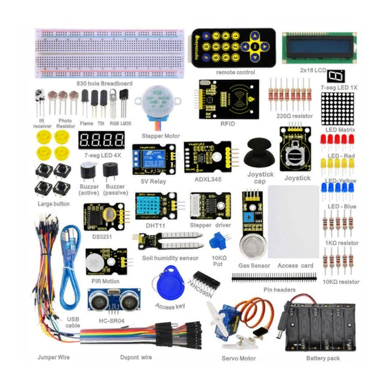
1. Introduction keyestudio super learning kit is suitable for Arduino enthusiasts. This kit includes 32 projects with detailed tutorials, starting from the basics to more complex projects. Different from other kits, it adds some functional modules, such as RFID, temperature and humidity module. There is connection diagram and code for each project, making it easy for you to learn. - Page 4 220 Ω Resistor 10K Ω Resistor 1K Ω resistor 10K Ω Potentiometer Buzzer (Active) Buzzer (Passive) Large Button Switch www.keyestudio.com...
- Page 5 Ball Tilt Sensor Photo Resistor Flame Sensor LM35 Temp Sensor IC 74HC595N 16-pin DIP 7-seg LED Segment Display 7-seg LED Segment Display 8*8 LED Matrix www.keyestudio.com...
- Page 6 2x16 LCD display IR Receiver IR Remote Control Servo Motor Stepper Driver Stepper Motor Joystick Module www.keyestudio.com...
- Page 7 Relay Module PIR Motion Sensor Analog Gas Sensor ADXL345 Three Axis Acceleration Module HC-SR04 Ultrasonic Sensor DS3231 Clock Module www.keyestudio.com...
- Page 8 DHT11 Temperature and Humidity Sensor Soil Humidity Sensor RC522 RFID Module RFID Card Access Key Pin Headers www.keyestudio.com...
-
Page 9: Project List
830-hole Breadboard Dupont Wire Jumper Wire 6-cell AA Battery Case USB Cable 3. Project List Project 1: Hello World Project 2: LED Blinking Project 3: PWM Project 4: Traffic Light Project 5: LED Chasing Effect Project 6: Button-controlled LED Project 7: Active Buzzer www.keyestudio.com... -
Page 10: Project Details
Project 8: Passive Buzzer Project 9: RGB LED Project 10: Photo Resistor Project 11: Flame Sensor Project 12: LM35 Temperature Sensor Project 13: Tilt Switch Project 14: IR Remote Control Project 15: Analog Value Reading Project 16: 74HC595 Project 17: 1-digit LED Segment Display... - Page 11 Sample Code After installing driver for Arduino, let's open Arduino software and compile code that enables Arduino to print "Hello World!" under your instruction. Of course, you can compile code for Arduino to continuously echo "Hello World!" without instruction. A simple If () statement will do the instruction trick.
- Page 12 Test Result Click to open the serial monitor, input an “ R”, LED 13 will blink once, PC will receive the information from Arduino: Hello World After choosing the proper port, the experiment is easy for you! www.keyestudio.com...
-
Page 13: Project 2: Led Blinking
Project 2: LED Blinking Introduction Blinking LED experiment is quite simple. In the "Hello World!" program, we have come across LED. This time, we are going to connect an LED to one of the digital pins rather than using LED13 soldered to the board. - Page 14 Connection for UNO R3: Connection for 2560 R3: www.keyestudio.com...
-
Page 15: Project 3: Pwm
Sample Code ////////////////////////////////////////////////////////// int ledPin = 10; // define digital pin 10. void setup() pinMode(ledPin, OUTPUT);// define pin with LED connected as output. void loop() digitalWrite(ledPin, HIGH); // set the LED on. delay(1000); // wait for a second. digitalWrite(ledPin, LOW); // set the LED off. - Page 16 Introduction PWM, short for Pulse Width Modulation, is a technique used to encode analog signal level into digital ones. A computer cannot output analog voltage but only digital voltage values such as 0V or 5V. So we use a high resolution counter to encode a specific analog signal level by modulating the duty cycle of PMW.
- Page 17 1. The amplitude of pulse width (minimum / maximum) 2. The pulse period (The reciprocal of pulse frequency in one second) 3. The voltage level(such as:0V-5V) There are 6 PMW interfaces on Arduino, namely digital pin 3, 5, 6, 9, 10, and 11. In previous experiments, we have done "button-controlled LED", using digital signal to control digital pin,...
- Page 18 Connection for 2560 R3: Sample Code In the program compiling process, we will use the analogWrite (PWM interface, analog value) function. In this experiment, we will read the analog value of the potentiometer and assign the value to PWM port, so there will be corresponding change to the brightness of the LED. One final part will display the analog value on the screen.
- Page 19 Serial.println(val);// display value of val analogWrite(ledpin,val/4);// turn on LED and set up brightness ( maximum output of PWM is 255) delay(10);// wait for 0.01 second...
-
Page 20: Project 4: Traffic Light
Project 4: Traffic Light Introduction In the previous program, we have done the LED blinking experiment with one LED. Now, it’s time to up the stakes to do a bit more complicated experiment-traffic light. Actually, these two experiments are similar. While in this traffic light experiment, we use three LEDs with different colors rather than an LED. - Page 21 Circuit Connection Connection for UNO R3: Connection for 2560 R3: www.keyestudio.com...
- Page 22 Sample Code Since it is a simulation of traffic lights, the blinking time of each LED should be the same with those in traffic lights system. In this program, we use Arduino delay () function to control delay time, which is much simpler than C language.
-
Page 23: Project 5: Led Chasing Effect
Project 5: LED Chasing Effect Introduction We can see many billboards composed of colorful LEDs. They are constantly changing to form various effects. In this experiment, we compile a program to simulate chase effect. Hardware Required Red LED*6 220Ω Resistor *6... - Page 24 Connection for 2560 R3: Sample Code ////////////////////////////////////////////////////////// int BASE = 2 ; // the I/O pin for the first LED int NUM = 6; // number of LEDs void setup() for (int i = BASE; i < BASE + NUM; i ++) pinMode(i, OUTPUT);...
-
Page 25: Project 6: Button-Controlled Led
(int i = BASE; i < BASE + NUM; i ++) digitalWrite(i, HIGH); // set I/O pins as “high”, turn on LEDs one by one delay(200); // delay ////////////////////////////////////////////////////////// Result You can see the LEDs blink by sequence. - Page 26 Hardware Required Button switch*1 Red M5 LED*1 220ΩResistor*1 10KΩ Resistor*1 Breadboard*1 Breadboard Jumper Wires Circuit Connection Connection for UNO R3: Connection for 2560 R3: www.keyestudio.com...
- Page 27 Sample Code Now, let's begin the compiling. When the button is pressed, the LED will be on. Based on the previous study, the coding should be easy for you. In this program, we add a statement of judgment. Here, we use an if () statement.
-
Page 28: Project 7: Active Buzzer
7 and assign if to val if(val==LOW)// check if the button is pressed, if yes, turn on the LED { digitalWrite(ledpin,LOW);} else { digitalWrite(ledpin,HIGH);} ////////////////////////////////////////////////////////// Test Result When the button is pressed, LED is on, otherwise, LED remains off. In this way, the button controlled LED experiment is completed. - Page 29 Hardware Required Buzzer*1 Key *1 Breadboard*1 Breadboard Jumper Wires Circuit Connection Connection for UNO R3: Connection for 2560 R3: www.keyestudio.com...
- Page 30 When connecting the circuit, pay attention to the positive and negative poles of the buzzer. In the photo, you can see there are red and black lines. When the circuit is finished, you can begin the programming. Sample Code Program is simple.
-
Page 31: Project 8: Passive Buzzer
Project 8: Passive Buzzer Introduction We can use Arduino to make many interactive works. The most commonly used one is acoustic-optic display. All the previous experiment has something to do with LED. However, the circuit in this experiment can produce sound. Normally, the experiment is done with a buzzer but not a speaker while buzzer is more simpler and easier to use. - Page 32 Connection for 2560 R3: www.keyestudio.com...
- Page 33 Sample Code ////////////////////////////////////////////////////////// int buzzer=8;// select digital IO pin for the buzzer void setup() pinMode(buzzer,OUTPUT);// set digital IO pin pattern, OUTPUT to be output void loop() { unsigned char i,j;//define variable while(1) { for(i=0;i<80;i++)// output a frequency sound { digitalWrite(buzzer,HIGH);// sound delay(1);//delay1ms...
-
Page 34: Project 9: Rgb Led
Project 9: RGB LED Introduction Tricolor principle to display various colors; PWM controlling ports to display full color; Can be driven directly by Arduino PWM interface. Hardware Required Arduino Board* 1 USB Cable * 1 RGB LED * 1... - Page 35 Circuit Connection Connection for UNO R3: Connection for 2560 R3: www.keyestudio.com...
- Page 36 Sample Code ////////////////////////////////////////////////////////// int redpin = 11; //select the pin for the red LED int bluepin =10; // select the pin for the blue LED int greenpin =9;// select the pin for the green LED int val; void setup() { pinMode(redpin, OUTPUT);...
-
Page 37: Project 10: Photo Resistor
Project 10: Photo Resistor Introduction After completing all the previous experiments, you may acquire some basic understanding and knowledge about Arduino application. We have introduced digital input and output, analog input and PWM. Now, let’s begin the learning of sensor applications. - Page 38 Hardware Required Photo Resistor*1 Red M5 LED*1 10KΩ Resistor*1 220Ω Resistor*1 Breadboard*1 Breadboard Jumper Wires Circuit Connection Connection for UNO R3: www.keyestudio.com...
- Page 39 Connection for 2560 R3: Sample Code After wiring, let's begin the program compiling. The program is similar to the PWM. For change detail, please refer to the Sample Code below. ////////////////////////////////////////////////////////// int potpin=0;// initialize analog pin 0, connected with photovaristor int ledpin=11;// initialize digital pin 11, output regulating the brightness of LED...
-
Page 40: Project 11: Flame Sensor
0.01 ////////////////////////////////////////////////////////// Test Result After downloading the program, you can change the light strength around the photovaristor, and see the corresponding brightness change of the LED. Photovaristors has various applications in our everyday. You can make other interesting interactive projects based on this one. - Page 41 Hardware Required Flame Sensor *1 Buzzer *1 10K Resistor *1 Breadboard Jumper Wires Circuit Connection 1)Connecting buzzer: Connect the controller board, prototype board, breadboard and USB Cable according to the Arduino tutorial. Connect the buzzer to digital pin 8.
- Page 42 Connection for MEGA 2560: www.keyestudio.com...
- Page 43 Experiment Principle When it's approaching a fire, the voltage value read from the analog port will differ. If you use a multimeter, you can see that when there is no fire approaching, the voltage it reads is around 0.3V;...
-
Page 44: Project 12: Lm35 Temperature Sensor
Project 12: LM35 Temperature Sensor Introduction LM35 is a common and easy-to-use temperature sensor. It does not require other hardware. You just need an analog port to make it work. The difficulty lies in compiling the code to convert the analog value it reads into Celsius temperature. - Page 45 Connection for UNO R3: Connection for 2560 R3: www.keyestudio.com...
- Page 46 Sample Code ////////////////////////////////////////////////////////// int potPin = 0; // initialize analog pin 0 for LM35 temperature sensor void setup() Serial.begin(9600);// set baud rate at”9600” void loop() int val;// define variable int dat;// define variable val=analogRead(0);// read the analog value of the sensor and assign it to val dat=(125*val)>>8;// temperature calculation formula...
-
Page 47: Project 13: Tilt Switch
Project 13: Tilt Switch Introduction Tilt switch controlling the LED on and off. Hardware Required Ball switch*1 Led *1 220Ω Resistor*1 10KΩ resistor*1 Breadboard Jumper Wires Circuit Connection Connection for R3: www.keyestudio.com... - Page 48 Connection for 2560 R3: Connect the controller board, shield, breadboard and USB cable according to Arduino tutorial. Connect the LED to digital pin 8, ball switch to analog pin 5. Experiment Principle When one end of the switch is below horizontal position, the switch is on. The voltage of the analog port is about 5V (1023 in binary).
-
Page 49: Project 14: Ir Remote Control
5 if(i>512)// if larger that 512(2.5V) digitalWrite(8,LOW);// turn on LED else// otherwise digitalWrite(8,HIGH);// turn off LED ////////////////////////////////////////////////////////// Test Result Hold the breadboard with your hand. Tilt it to a certain extent, the LED will be on. If there is no tilt, the LED will be off. - Page 50 Introduction What is an infrared receiver? The signal from the infrared remote controller is a series of binary pulse code. To avoid the other infrared signal interference during the wireless transmission, the signal is pre-modulate at a specific carrier frequency and then send out by an infrared emission diode. The infrared receiving device needs to filter out other waves and receive signals at that specific frequency and to modulate it back to binary pulse code, known as demodulation.
- Page 51 Hardware Required Infrared Remote Controller *1 Infrared Receiver *1 LED *6 220ΩResistor *6 Multi-color Breadboard Wires Circuit Connection First, connect the controller board; then connect the infrared receiver as the above mentioned, connect VOUT to digital pin 11, connect the LEDs with resistors and connect the resistors to pin 2,3,4,5,6,7.
- Page 52 Connection for 2560 R3: Experimental Principle If you want to decode the code from the remote controller, you must first know how it's coded. The coding method we use here is NEC protocol. Below is a brief introduction. • NEC protocol: Features:...
- Page 53 • Pulse transmitted when button is pressed and immediately released The picture above shows a typical pulse train of the NEC protocol. With this protocol the LSB is transmitted first. In this case Address $59 and Command $16 is transmitted. A message is started by a 9ms AGC burst, which was used to set the gain of the earlier IR receivers.
- Page 54 Sample Code ////////////////////////////////////////////////////////// #include <IRremote.h> int RECV_PIN = 11; int LED1 = 2; int LED2 = 3; int LED3 = 4; int LED4 = 5; int LED5 = 6; int LED6 = 7; long on1 = 0x00FF6897; long off1 = 0x00FF9867;...
- Page 55 Serial.print("Decoded SONY: "); else if (results->decode_type == RC5) Serial.print("Decoded RC5: "); else if (results->decode_type == RC6) Serial.print("Decoded RC6: "); Serial.print(results->value, HEX); Serial.print(" ("); Serial.print(results->bits, DEC); Serial.println(" bits)"); Serial.print("Raw ("); Serial.print(count, DEC); Serial.print("): "); for (int i = 0; i < count; i++) if ((i % 2) == 1) { Serial.print(results->rawbuf[i]*USECPERTICK, DEC);...
- Page 56 Serial.begin(9600); irrecv.enableIRIn(); // Start the receiver int on = 0; unsigned long last = millis(); void loop() if (irrecv.decode(&results)) // If it's been at least 1/4 second since the last // IR received, toggle the relay if (millis() - last > 250) on = !on;...
- Page 57 LOW); last = millis(); irrecv.resume(); // Receive the next value ////////////////////////////////////////////////////////// Note:add IRremote folder into installation directory \Arduino\compiler libraries, or you will fail to compile it. Infrared remote library: https://github.com/shirriff/Arduino-IRremote Program Function Decode the coded pulse signal emitted by the remote controller, then execute corresponding action according to the results of the decoding.
-
Page 58: Project 15: Analog Value Reading
Project 15: Analog Value Reading Introduction In this experiment, we will begin the study of analog I/O interfaces. On an Arduino, there are 6 analog interfaces numbered from 0 to 5. These 6 interfaces can also be used as digital ones numbered as 14-19. - Page 59 Connection for 2560 R3: www.keyestudio.com...
- Page 60 Sample Code The program compiling is simple. An analogRead () Statement can read the value of the interface. The A/D acquisition of Arduino 328 is in 10 bits, so the value it reads is among 0 to 1023. One difficulty in this project is to display the value on the screen, which is actually easy to learn.
- Page 61 The experiment is now completed. Thank you! ******************************************************************************* Project 16: 74HC595 Introduction To put it simply, 74HC595 is a combination of 8-digit shifting register, memorizer and equipped with tri-state output. Here, we use it to control 8 LEDs. You may wonder why use a 74HC595 to control LED? Well, think about how many I/O it takes for an Arduino to control 8 LEDs? Yes, 8.
- Page 62 Hardware Required 74HC595 chip*1 Red M5 LED*4 Green M5 LED*4 220Ω Resistor*8 Breadboard*1 Breadboard Jumper Wires Circuit Connection Connection for UNO R3: Note: for pin 13 OE port of 74HC595, it should be connected to GND. www.keyestudio.com...
- Page 63 Connection for 2560 R3: The circuit may seem complicated, but once you wire it in order, you will find it more easier! Sample Code ////////////////////////////////////////////////////////// int data = 2;// set pin 14 of 74HC595as data input pin SI int clock = 5;// set pin 11 of 74hc595 as clock pin SCK int latch = 4;// set pin 12 of 74hc595 as output latch RCK...
-
Page 64: Project 17: 1-Digit Led Segment Display
= 0; i < 256; i++) updateLEDs(i); delay(500); void updateLEDs(int value) digitalWrite(latch, LOW);// shiftOut(data, clock, MSBFIRST, ~value);// serial data “output”, high level first digitalWrite(latch, HIGH);// latch ////////////////////////////////////////////////////////// Test Result After downloading the program, you can see 8 LEDs display 8-bit binary number. - Page 65 8-segment display has one more LED unit ( for decimal point display) than 7-segment one. According to the wiring method of LED units, LED segment display can be divided into common anode display and common cathode display. Common anode display refers to the one that combine all the anodes of LED units into one common anode (COM).
- Page 66 Connection for 2560 R3: www.keyestudio.com...
- Page 67 Sample Code There are seven segments for numerical display, one for decimal point display. Corresponding segments will be turned on when displaying certain numbers. For example, when displaying number 1, b and c segments will be turned on. We compile a subprogram for each number, and compile the main program to display one number every 2 seconds, cycling display number 0 ~ 9.
- Page 68 // display number 3 {digitalWrite(g,HIGH); digitalWrite(a,HIGH); digitalWrite(b,HIGH); digitalWrite(c,HIGH); digitalWrite(d,HIGH); digitalWrite(dp,LOW); digitalWrite(f,LOW); digitalWrite(e,LOW); void digital_4(void) // display number 4 {digitalWrite(c,HIGH); digitalWrite(b,HIGH); digitalWrite(f,HIGH); digitalWrite(g,HIGH); digitalWrite(dp,LOW); digitalWrite(a,LOW); digitalWrite(e,LOW); digitalWrite(d,LOW); void digital_5(void) // display number 5 unsigned char j;...
- Page 69 // display number 7 unsigned char j; for(j=5;j<=7;j++) digitalWrite(j,HIGH); digitalWrite(dp,LOW); for(j=8;j<=11;j++) digitalWrite(j,LOW); void digital_8(void) // display number 8 unsigned char j; for(j=5;j<=11;j++) digitalWrite(j,HIGH); digitalWrite(dp,LOW); void digital_9(void) // display number 5 unsigned char j;...
- Page 70 0 delay(1000);// wait for 1s digital_1();// display number 1 delay(1000);// wait for 1s digital_2();// display number 2 delay(1000); // wait for 1s digital_3();// display number 3 delay(1000); // wait for 1s digital_4();// display number 4 delay(1000);...
-
Page 71: Project 18: 4-Digit Led Segment Display
Project 18: 4-digit LED Segment Display Introduction In this experiment, we use an Arduino to drive a common cathode, 4-digit, 7-segment LED display. For LED display, current-limiting resistors are indispensable. There are two wiring methods for Current-limiting resistor. One is to connect one resistor for each cathode end, 4 in total for d1-d4 cathode. - Page 72 Manual for LED Segment Display: Connection for UNO R3: www.keyestudio.com...
- Page 73 Connection for 2560 R3: Sample Code ////////////////////////////////////////////////////////// // display 1234 // select pin for cathode int a = 1; int b = 2; int c = 3; int d = 4; int e = 5; int f = 6;...
- Page 74 OUTPUT); pinMode(d, OUTPUT); pinMode(e, OUTPUT); pinMode(f, OUTPUT); pinMode(g, OUTPUT); pinMode(dp, OUTPUT); ///////////////////////////////////////////////////////////// void loop() Display(1, 1); Display(2, 2); Display(3, 3); Display(4, 4); /////////////////////////////////////////////////////////////// void WeiXuan(unsigned char n)// switch(n) case 1: digitalWrite(d1,LOW); digitalWrite(d2, HIGH); digitalWrite(d3, HIGH); digitalWrite(d4, HIGH); break;...
- Page 75 HIGH); digitalWrite(d4, LOW); break; default : digitalWrite(d1, HIGH); digitalWrite(d2, HIGH); digitalWrite(d3, HIGH); digitalWrite(d4, HIGH); break; void Num_0() digitalWrite(a, HIGH); digitalWrite(b, HIGH); digitalWrite(c, HIGH); digitalWrite(d, HIGH); digitalWrite(e, HIGH); digitalWrite(f, HIGH); digitalWrite(g, LOW); digitalWrite(dp,LOW); void Num_1() digitalWrite(a, LOW); digitalWrite(b, HIGH);...
- Page 76 Num_3() digitalWrite(a, HIGH); digitalWrite(b, HIGH); digitalWrite(c, HIGH); digitalWrite(d, HIGH); digitalWrite(e, LOW); digitalWrite(f, LOW); digitalWrite(g, HIGH); digitalWrite(dp,LOW); void Num_4() digitalWrite(a, LOW); digitalWrite(b, HIGH); digitalWrite(c, HIGH); digitalWrite(d, LOW); digitalWrite(e, LOW); digitalWrite(f, HIGH); digitalWrite(g, HIGH); digitalWrite(dp,LOW); void Num_5() digitalWrite(a, HIGH);...
- Page 77 HIGH); digitalWrite(g, HIGH); digitalWrite(dp,LOW); void Num_7() digitalWrite(a, HIGH); digitalWrite(b, HIGH); digitalWrite(c, HIGH); digitalWrite(d, LOW); digitalWrite(e, LOW); digitalWrite(f, LOW); digitalWrite(g, LOW); digitalWrite(dp,LOW); void Num_8() digitalWrite(a, HIGH); digitalWrite(b, HIGH); digitalWrite(c, HIGH); digitalWrite(d, HIGH); digitalWrite(e, HIGH); digitalWrite(f, HIGH); digitalWrite(g, HIGH); digitalWrite(dp,LOW);...
- Page 78 LOW); digitalWrite(e, LOW); digitalWrite(f, LOW); digitalWrite(g, LOW); digitalWrite(dp,LOW); void pickNumber(unsigned char n)// select number switch(n) case 0:Num_0(); break; case 1:Num_1(); break; case 2:Num_2(); break; case 3:Num_3(); break; case 4:Num_4(); break; case 5:Num_5(); break; case 6:Num_6(); break; case 7:Num_7();...
-
Page 79: Project 19: 8*8 Led Matrix
Result Download the above code to the controller board, you can see the LED display shows the number 1234. Note: if it’s not displaying correctly, check the wiring. The experiment is over. Thank you! ****************************************************************************** Project 19: 8*8 LED Matrix... - Page 80 The external view of a dot-matrix is shown as follows: The display principle of the 8*8 dot-matrix: The 8*8 dot-matrix is made up of sixty-four LEDs, and each LED is placed at the cross point of a row and a column. When the electrical level of a certain row is 1 and the electrical level of a certain column is 0, the corresponding LED will lighten.
- Page 81 Connection for UNO R3: Connection for 2560 R3: Sample Code for displaying “0” ////////////////////////////////////////////////////////// // set an array to store character of “0” unsigned char Text[]={0x00,0x1c,0x22,0x22,0x22,0x22,0x22,0x1c}; void Draw_point(unsigned char x,unsigned char y)// point drawing function { clear_(); digitalWrite(x+2, HIGH);...
- Page 82 & 0x01)Draw_point(j,i); data>>=1; void setup(){ int i = 0 ; for(i=2;i<18;i++) pinMode(i, OUTPUT); clear_(); void loop() { show_num(); void clear_(void)// clear screen {for(int i=2;i<10;i++) digitalWrite(i, LOW);...
-
Page 83: Project 20: 1602 Lcd
Project 20: 1602 LCD Introduction In this experiment, we use an Arduino to drive the 1602 LCD. 1602 LCD has wide applications. In the beginning, 1602 LCD uses a HD44780 controller. Now, almost all 1602 LCD module uses a compatible IC, so their features are basically the same. - Page 84 Interface Description: 1. two power sources, one for module power, another one for back light, generally use 5V. In this project, we use 3.3V for back light. 2. VL is the pin for adjusting contrast ratio; it usually connects a potentiometer(no more than 5KΩ) in series for its adjustment.
- Page 85 8-bit Connection Method: Connection for UNO R3: www.keyestudio.com...
- Page 86 Connection for 2560 R3: Sample Code A: ////////////////////////////////////////////////////////// int DI = 12; int RW = 11; int DB[] = {3, 4, 5, 6, 7, 8, 9, 10};// use array to select pin for bus int Enable = 2; void LcdCommandWrite(int value) { // define all pins int i = 0;...
- Page 87 HIGH); digitalWrite(RW, LOW); for (i=DB[0]; i <= DB[7]; i++) { digitalWrite(i,value & 01); value >>= 1; digitalWrite(Enable,LOW); delayMicroseconds(1); digitalWrite(Enable,HIGH); delayMicroseconds(1); digitalWrite(Enable,LOW); delayMicroseconds(1); // wait for 1ms void setup (void) { int i = 0; for (i=Enable; i <= DI; i++) { pinMode(i,OUTPUT);...
- Page 88 (void) { LcdCommandWrite(0x01); // clear the scree, cursor position returns to 0 delay(10); LcdCommandWrite(0x80+3); delay(10); // write in welcome message LcdDataWrite('W'); LcdDataWrite('e'); LcdDataWrite('l'); LcdDataWrite('c'); LcdDataWrite('o'); LcdDataWrite('m'); LcdDataWrite('e'); LcdDataWrite(' '); LcdDataWrite('t'); LcdDataWrite('o'); delay(10); LcdCommandWrite(0xc0+1); // set cursor position at second line, second position delay(10);...
- Page 89 LcdDataWrite('n'); LcdDataWrite('g'); LcdDataWrite('y'); LcdDataWrite('i'); delay(3000); LcdCommandWrite(0x02); // set mode as new characters replay old ones, where there is no new ones remain the same delay(10); LcdCommandWrite(0x80+5); // set cursor position at first line, sixth position delay(10); LcdDataWrite('t'); LcdDataWrite('h'); LcdDataWrite('e');...
- Page 90 Connection for 2560 R3: After the connection, upload below code to the controller board and see how it goes. Sample Code B: ////////////////////////////////////////////////////////// LiquidCrystal Library - Hello World Demonstrates the use a 16x2 LCD display. The LiquidCrystal library works with all LCD displays that are compatible with the Hitachi HD44780 driver.
- Page 91 * 10K resistor: * ends to +5V and ground * wiper to LCD VO pin (pin 3) Library originally added 18 Apr 2008 by David A. Mellis library modified 5 Jul 2009 by Limor Fried (http://www.ladyada.net) example added 9 Jul 2009...
-
Page 92: Project 21: 9G Servo Control
Project 21: 9g Servo Control Introduction Servomotor is a position control rotary actuator. It mainly consists of housing, circuit board, core-less motor, gear and position sensor. The receiver or MCU outputs a signal to the servomotor. The motor has a built-in reference circuit that gives out reference signal, cycle of 20ms and width of 1.5ms. - Page 93 The rotate angle of the servo motor is controlled by regulating the duty cycle of the PWM(Pulse-Width Modulation) signal. The standard cycle of the PWM signal is 20ms(50Hz). Theoretically, the width is distributed between 1ms-2ms, but in fact, it's between 0.5ms-2.5ms.
- Page 94 Connection for 2560 R3: Connect the motor to digital pin 9. www.keyestudio.com...
- Page 95 Compile a program to control the motor to rotate in the commanded angle, and display the angle on the screen. Sample Code A ////////////////////////////////////////////////////////// int servopin=9;// select digital pin 9 for servomotor signal line int myangle;// initialize angle variable int pulsewidth;// initialize width variable...
- Page 96 Method 2: Let's first take a look at the Arduino built-in servo function and some common statements. 1. attach(interface)——select pin for servo, can only use pin 9 or 10. 2. write ( angle) ——used to control the rotate angle of the servo, can set the angle among 0 degree to 180 degree.
-
Page 97: Project 22: 5V Stepper Motor
Project 22: 5V Stepper Motor Introduction A stepper motor is an electromechanical device which can convert electrical pulses into discrete mechanical movements. The shaft or spindle of a stepper motor rotates in discrete step increments when electrical command pulses are applied to it in the proper sequence. The motors rotation has several direct relationships to these applied input pulses. - Page 98 • A wide range of rotational speeds can be realized as the speed is proportional to the frequency of the input pulses. Parameters of Stepper Motor 28BYJ-48 Model: 28BYJ-48 Rated Voltage: 5VDC Number of Phase: 4 Speed Variation Ratio: 1/64 Stride Angle: 5.625°...
- Page 99 Connection for 2560 R3: Sample Code ////////////////////////////////////////////////////////// #include <Stepper.h> #define STEPS 100 Stepper stepper(STEPS, 8, 9, 10, 11); int previous = 0; void setup() stepper.setSpeed(90); void loop() int val = analogRead(0); stepper.step(val - previous); previous = val; ////////////////////////////////////////////////////////// www.keyestudio.com...
-
Page 100: Project 23: Pir Motion Sensor
Project 23: PIR Motion Sensor Introduction Pyroelectric infrared motion sensor can detect infrared signals from a moving person or moving animal, and output switching signals. It can be applied to a variety of occasions to detect the movement of human body. Conventional pyroelectric infrared sensors require body pyroelectric infrared detector, professional chip, complex peripheral circuit, so it is more bigger with complex circuit, and lower reliability. - Page 101 Connection for UNO R3: Connection for MEGA 2560 R3: Sample Code ////////////////////////////////////////////////////////// byte sensorPin = 3; byte indicator = 13; void setup() pinMode(sensorPin,INPUT); pinMode(indicator,OUTPUT); Serial.begin(9600); www.keyestudio.com...
-
Page 102: Project 24: Analog Gas Sensor
= digitalRead(sensorPin); digitalWrite(indicator,state); if(state == 1)Serial.println("Somebody is in this area!"); else if(state == 0)Serial.println("No one!"); delay(500); ////////////////////////////////////////////////////////// Project 24: Analog Gas Sensor Introduction This analog gas sensor - MQ2 is used in gas leakage detecting equipment in consumer electronics and industrial markets. - Page 103 Stable and long lifespan Size: 49.7*20mm Weight: 8g Circuit Connection Connection for UNO R3: Connection for MEGA 2560 R3: Sample Code ////////////////////////////////////////////////////////// void setup() Serial.begin(9600); //Set serial baud rate to 9600 bps www.keyestudio.com...
-
Page 104: Project 25: Adxl345 Three Axis Acceleration Module
{int val; val=analogRead(0);//Read Gas value from analog 0 Serial.println(val,DEC);//Print the value to serial port delay(100); ////////////////////////////////////////////////////////// Project 25: ADXL345 Three Axis Acceleration Module Introduction The ADXL345 is a small, thin, low power, 3-axis MEMS accelerometer with high resolution (13-bit) measurement at up to +-16 g. - Page 105 Circuit Connection Connection for UNO R3: Connection for MEGA 2560 R3: www.keyestudio.com...
- Page 106 Sample Code /////////////////////////////////////////////////////////////////////////////////////////////////////////////////// The circuit: VCC: 5V GND: ground SCL: UNO SLC SDA: UNO SDA This example code is in the public domain. #include <Wire.h> // Registers for ADXL345 #define ADXL345_ADDRESS (0xA6 >> 1) // address for device is 8 bit but shift to the...
- Page 107 // Connect to device Wire.beginTransmission(address); // Request data from slave // Count stands for number of bytes to request Wire.requestFrom(address, count); while(Wire.available()) // slave may send less than requested char c = Wire.read(); // receive a byte as character data[i] = c;...
- Page 108 // initialise and start everything void setup() { Wire.begin(); Serial.begin(9600); for(int i=0; i<3; ++i) { accelerometer_data[i] = 0; init_adxl345(); void loop() { read_adxl345(); Serial.print("ACCEL: "); Serial.print(float(accelerometer_data[0])*3.9/1000);//3.9mg/LSB scale factor in 13-bit mode Serial.print("\t"); Serial.print(float(accelerometer_data[1])*3.9/1000); Serial.print("\t"); Serial.print(float(accelerometer_data[2])*3.9/1000); Serial.print("\n"); delay(100); //////////////////////////////////////////////////////////////////////////////////////////////////////////////////// www.keyestudio.com...
-
Page 109: Project 26: Hc-Sr04 Ultrasonic Sensor
Project 26: HC-SR04 Ultrasonic Sensor Introduction The HC-SR04 Ultrasonic Sensor is a very affordable proximity/distance sensor that is mainly used for object avoidance in various robotics projects. It essentially gives your Arduino eyes / spacial awareness and can prevent your robot from crashing or falling off a table. It has also been used in turret applications, water level sensing, and even as a parking sensor. - Page 110 Connection for MEGA 2560 R3: Sample Code ////////////////////////////////////////////////////////// VCC to arduino 5v GND to arduino GND Echo to Arduino pin 7 Trig to Arduino pin 8 #define echoPin 7 // Echo Pin #define trigPin 8 // Trigger Pin #define LEDPin 13 // Onboard LED int maximumRange = 200;...
- Page 111 // Duration used to calculate distance void setup() { Serial.begin (9600); pinMode(trigPin, OUTPUT); pinMode(echoPin, INPUT); pinMode(LEDPin, OUTPUT); // Use LED indicator (if required) void loop() { /* The following trigPin/echoPin cycle is used to determine the distance of the nearest object by bouncing soundwaves off of it.
-
Page 112: Project 27: Joystick Module
Project 27: Joystick Module Introduction Lots of robot projects need joystick. This module provides an affordable solution. By simply connecting to two analog inputs, the robot is at your commands with X, Y control. It also has a switch that is connected to a digital pin. This joystick module can be easily connected to Arduino by IO Shield. - Page 113 Connection for MEGA 2560 R3: Sample Code ////////////////////////////////////////////////////////// int JoyStick_X = 0; //x int JoyStick_Y = 1; //y int JoyStick_Z = 3; //key void setup() pinMode(JoyStick_Z, INPUT); Serial.begin(9600); // 9600 bps void loop() int x,y,z; x=analogRead(JoyStick_X); y=analogRead(JoyStick_Y); z=digitalRead(JoyStick_Z); Serial.print(x ,DEC);...
-
Page 114: Project 28: 5V Relay Module
Project 28: 5V Relay Module Introduction This single relay module can be used in interactive projects. This module uses SONGLE 5v high-quality relay. It can also be used to control the lighting, electrical and other equipment. The modular design makes it easy to expand with the Arduino Board (not included). - Page 115 Connection for UNO R3: Connection for MEGA 2560 R3: Sample Code ////////////////////////////////////////////////////////// int Relay = 8; void setup() pinMode(13, OUTPUT); //Set Pin13 as output digitalWrite(13, HIGH); //Set Pin13 High www.keyestudio.com...
-
Page 116: Project 29: Ds3231 Clock Module
OUTPUT); //Set Pin3 as output void loop() digitalWrite(Relay, HIGH); //Turn off relay delay(2000); digitalWrite(Relay, LOW); //Turn on relay delay(2000); ////////////////////////////////////////////////////////// Project 29: DS3231 Clock Module Introduction DS3231 is equipped with integrated TCXO and crystal, which makes it a cost-effective I2C real time clock with high precision. - Page 117 Specification • Temperature Range: -40 to +85; • Timing Accuracy : ± 5ppm (±0.432 seconds / day) • Provide battery backup for continuous timing • Low power consumption • Device package and function compatible with DS3231 • Complete clock calendar function contains seconds and minutes, hour, week, date, month, and year timing and provides leap year compensation until 2100.
- Page 118 Connection for MEGA 2560 R3: Sample Code ////////////////////////////////////////////////////////// #include <Wire.h> #include "DS3231.h" DS3231 RTC; //Create the DS3231 object char weekDay[][4] = {"Sun", "Mon", "Tue", "Wed", "Thu", "Fri", "Sat" }; //year, month, date, hour, min, sec and week-day(starts from 0 and goes to 6) //writing any non-existent time-data may interfere with normal operation of the RTC.
- Page 119 Serial.print(now.minute(), DEC); Serial.print(':'); Serial.print(now.second(), DEC); Serial.println(); Serial.print(weekDay[now.dayOfWeek()]); Serial.println(); delay(1000); ////////////////////////////////////////////////////////// Before compiling the code, you’d better put DS3231 library under file into Arduino catalogue. Test Result Done uploading the code to arduino, open the serial monitor and get the following results:...
-
Page 120: Project 30: Dht11 Temperature And Humidity Sensor
Project 30: DHT11 Temperature and Humidity Sensor Introduction This DHT11 Temperature and Humidity Sensor features calibrated digital signal output with the temperature and humidity sensor complex. Its technology ensures high reliability and excellent long-term stability. A high-performance 8-bit microcontroller is connected. - Page 121 Circuit Connection Connection for UNO R3: Connection for MEGA 2560 R3: Sample Code Please download the DHT11Lib firstly. Or see the website ////////////////////////////////////////////////////////// #include <dht11.h> dht11 DHT; #define DHT11_PIN 4 void setup(){ Serial.begin(9600); Serial.println("DHT TEST PROGRAM "); Serial.print("LIBRARY VERSION: ");...
- Page 122 Serial.println("Type,\tstatus,\tHumidity (%),\tTemperature (C)"); void loop(){ int chk; Serial.print("DHT11, \t"); chk = DHT.read(DHT11_PIN); // READ DATA switch (chk){ case DHTLIB_OK: Serial.print("OK,\t"); break; case DHTLIB_ERROR_CHECKSUM: Serial.print("Checksum error,\t"); break; case DHTLIB_ERROR_TIMEOUT: Serial.print("Time out error,\t"); break; default: Serial.print("Unknown error,\t"); break; // DISPLAT DATA Serial.print(DHT.humidity,1);...
-
Page 123: Project 31: Soil Humidity Sensor
Project 31: Soil Humidity Sensor Introduction This is a simple soil humidity sensor aims to detect the soil humidity. If the soil is lack of water, the analog value output by the sensor will decrease; otherwise, it will increase. If you use this sensor to make an automatic watering device, it can detect whether your botany is thirsty so as to prevent it from withering when you go out. - Page 124 Circuit Connection Connection for UNO R3: Connection for MEGA 2560 R3: Sample Code ////////////////////////////////////////////////////////// # 0 ~300 dry soil # 300~700 humid soil # 700~950 in water void setup(){ www.keyestudio.com...
-
Page 125: Project 32: Rc522 Rfid Module
Serial.begin(57600); void loop(){ Serial.print("Moisture Sensor Value:"); Serial.println(analogRead(0)); delay(100); ////////////////////////////////////////////////////////// Project 32: RC522 RFID Module Introduction MF522-AN module adopts Philips MFRC522 original reader circuit chip design, easy to use, low cost, suitable for equipment development, development of advanced applications, the need for the user of RF card terminal design / production. - Page 126 Supported card types: mifare1 S50, mifare1 S70, mifare UltraLight, mifare Pro, mifare Desfire Dimension: 40mm * 60mm Environmental Operating Temperature: -20-80 degrees Celsius Environment Storage Temperature: -40-85 degrees Celsius 10. Relative Humidity: 5% -95% Circuit Connection Connection for UNO R3:...
- Page 127 Connection for 2560 R3: Sample Code ////////////////////////////////////////////////////////// #include <SPI.h> #define uchar unsigned char #define uint unsigned int #define MAX_LEN 16 const int chipSelectPin = 10;//if the controller is UNO,328,168 const int NRSTPD = 5; //MF522command word #define PCD_IDLE 0x00 //NO action;concel current command...
- Page 128 #define PICC_READ 0x30 // Reader Module #define PICC_WRITE 0xA0 // letter block #define PICC_DECREMENT 0xC0 #define PICC_INCREMENT 0xC1 #define PICC_RESTORE 0xC2 //Transfer data to buffer #define PICC_TRANSFER 0xB0 //Save buffer data #define PICC_HALT 0x50 //Dormancy //MF522 Error code returned when communication...
- Page 129 #define RxThresholdReg 0x18 #define DemodReg 0x19 #define Reserved11 0x1A #define Reserved12 0x1B #define MifareReg 0x1C #define Reserved13 0x1D #define Reserved14 0x1E #define SerialSpeedReg 0x1F //Page 2:CFG #define Reserved20 0x20 #define CRCResultRegM 0x21 #define CRCResultRegL 0x22 #define Reserved21 0x23 #define...
- Page 130 ={'T', 'e', 'n', 'g', ' ', 'B', 'o', 0, 0, 0, 0, 0, 0, 0, 0,0}; uchar sectorKeyA[16][16] = {{0xFF, 0xFF, 0xFF, 0xFF, 0xFF, 0xFF}, {0xFF, 0xFF, 0xFF, 0xFF, 0xFF, 0xFF}, {0xFF, 0xFF, 0xFF, 0xFF, 0xFF, 0xFF},...
- Page 131 = MFRC522_Anticoll(str); memcpy(serNum, str, 5); if (status == MI_OK) Serial.println("The card's number is : "); Serial.print(serNum[0],BIN); Serial.print(serNum[1],BIN); Serial.print(serNum[2],BIN); Serial.print(serNum[3],BIN); Serial.print(serNum[4],BIN); Serial.println(" "); // select card, return card capacity RC_size = MFRC522_SelectTag(serNum); if (RC_size != 0) // write data card blockAddr = 7;...
- Page 132 // read card blockAddr = 7; // data block 7 status MFRC522_Auth(PICC_AUTHENT1A, blockAddr, sectorNewKeyA[blockAddr/4], serNum); // authentication if (status == MI_OK) // read data blockAddr = blockAddr - 3 ; status = MFRC522_Read(blockAddr, str); if (status == MI_OK) Serial.println("Read from the card ,the data is : ");...
- Page 133 SPI.transfer(((addr<<1)&0x7E) | 0x80); val =SPI.transfer(0x00); digitalWrite(chipSelectPin, HIGH); return val; void SetBitMask(uchar reg, uchar mask) uchar tmp; tmp = Read_MFRC522(reg); Write_MFRC522(reg, tmp | mask); // set bit mask void ClearBitMask(uchar reg, uchar mask) uchar tmp; tmp = Read_MFRC522(reg); Write_MFRC522(reg, tmp & (~mask)); // clear bit mask void AntennaOn(void) uchar temp;...
- Page 134 MFRC522_Reset(void) Write_MFRC522(CommandReg, PCD_RESETPHASE); void MFRC522_Init(void) digitalWrite(NRSTPD,HIGH); MFRC522_Reset(); //Timer: TPrescaler*TreloadVal/6.78MHz = 24ms Write_MFRC522(TModeReg, 0x8D); //Tauto=1; f(Timer) = 6.78MHz/TPreScaler Write_MFRC522(TPrescalerReg, 0x3E); //TModeReg[3..0] + TPrescalerReg Write_MFRC522(TReloadRegL, 30); Write_MFRC522(TReloadRegH, 0); Write_MFRC522(TxAutoReg, 0x40); //100%ASK Write_MFRC522(ModeReg, 0x3D); //CRC initial value AntennaOn(); // open antenna uchar MFRC522_Request(uchar reqMode, uchar *TagType) uchar status;...
- Page 135 MFRC522_ToCard(uchar command, uchar *sendData, uchar sendLen, uchar *backData, uint *backLen) uchar status = MI_ERR; uchar irqEn = 0x00; uchar waitIRq = 0x00; uchar lastBits; uchar n; uint i; switch (command) case PCD_AUTHENT: // card key authentication irqEn = 0x12;...
- Page 136 Write_MFRC522(CommandReg, command); if (command == PCD_TRANSCEIVE) SetBitMask(BitFramingReg, 0x80); //StartSend=1,transmission of data starts // wait for the completion of data receiving i = 2000; // adjust i according to clock frequency, maximum waiting time of operating M1 is 25ms //CommIrqReg[7..0] //Set1 TxIRq RxIRq IdleIRq HiAlerIRq LoAlertIRq ErrIRq TimerIRq n = Read_MFRC522(CommIrqReg);...
- Page 137 (n == 0) n = 1; if (n > MAX_LEN) n = MAX_LEN; // read data which FIFO received for (i=0; i<n; i++) backData[i] = Read_MFRC522(FIFODataReg); else status = MI_ERR; //SetBitMask(ControlReg,0x80); //timer stops //Write_MFRC522(CommandReg, PCD_IDLE); return status; uchar MFRC522_Anticoll(uchar *serNum) uchar status;...
- Page 138 (status == MI_OK) // verify card sequence number for (i=0; i<4; i++) serNumCheck ^= serNum[i]; if (serNumCheck != serNum[i]) status = MI_ERR; //SetBitMask(CollReg, 0x80); //ValuesAfterColl=1 return status; void CalulateCRC(uchar *pIndata, uchar len, uchar *pOutData) uchar i, n; ClearBitMask(DivIrqReg, 0x04);...
- Page 139 // read CRC calculation result pOutData[0] = Read_MFRC522(CRCResultRegL); pOutData[1] = Read_MFRC522(CRCResultRegM); uchar MFRC522_SelectTag(uchar *serNum) uchar i; uchar status; uchar size; uint recvBits; uchar buffer[9]; //ClearBitMask(Status2Reg, 0x08); //MFCrypto1On=0 buffer[0] = PICC_SElECTTAG; buffer[1] = 0x70; for (i=0; i<5; i++) buffer[i+2] = *(serNum+i);...
- Page 140 // Verification commands + block address + sector password + card sequence number buff[0] = authMode; buff[1] = BlockAddr; for (i=0; i<6; i++) buff[i+2] = *(Sectorkey+i); for (i=0; i<4; i++) buff[i+8] = *(serNum+i); status = MFRC522_ToCard(PCD_AUTHENT, buff, 12, buff, &recvBits);...
- Page 141 = PICC_WRITE; buff[1] = blockAddr; CalulateCRC(buff, 2, &buff[2]); status = MFRC522_ToCard(PCD_TRANSCEIVE, buff, 4, buff, &recvBits); if ((status != MI_OK) || (recvBits != 4) || ((buff[0] & 0x0F) != 0x0A)) status = MI_ERR;...
- Page 142 CalulateCRC(buff, 2, &buff[2]); status = MFRC522_ToCard(PCD_TRANSCEIVE, buff, 4, buff,&unLen); ////////////////////////////////////////////////////////// Note: if you want to use MEGA 2560 R3, please in the code change const int chipSelectPin = 10;//if the controller is UNO,328,168 into const int chipSelectPin = 53;//if the controller is UNO,328,168...
Need help?
Do you have a question about the KS0077 and is the answer not in the manual?
Questions and answers